
Engineerblogger
Jan 16, 2013
John Maeda, President of the Rhode Island School of Design, delivers a funny and charming talk that spans a lifetime of work in art, design and technology, concluding with a picture of creative leadership in the future. Watch for demos of Maeda’s earliest work -- and even a computer made of people.
John Maeda is the president of the Rhode Island School of Design, where he is dedicated to linking design and technology. Through the software tools, web pages and books he creates, he spreads his philosophy of elegant simplicity.
Source: TED
Additional Information:
Showing posts with label Design. Show all posts
Showing posts with label Design. Show all posts
Wednesday, 16 January 2013
Monday, 7 January 2013
Leah Buechley: How to “sketch” with electronics
Engineerblogger
Jan 6, 2012
Designing electronics is generally cumbersome and expensive -- or was, until Leah Buechley and her team at MIT developed tools to treat electronics just like paper and pen. In this talk from TEDYouth 2011, Buechley shows some of her charming designs, like a paper piano you can sketch and then play.
Leah Buechley is an MIT electronics designer who mixes high and low tech to create smart and playful results.
Source: TED
Additional Information:
Jan 6, 2012
Designing electronics is generally cumbersome and expensive -- or was, until Leah Buechley and her team at MIT developed tools to treat electronics just like paper and pen. In this talk from TEDYouth 2011, Buechley shows some of her charming designs, like a paper piano you can sketch and then play.
Leah Buechley is an MIT electronics designer who mixes high and low tech to create smart and playful results.
Source: TED
Additional Information:
Friday, 3 August 2012
The first robot that mimics the water striders’ jumping abilities
Engineerblogger
The first bio-inspired microrobot capable of not just walking on water like the water strider – but continuously jumping up and down like a real water strider – now is a reality. Scientists reported development of the agile microrobot, which could use its jumping ability to avoid obstacles on reconnaissance or other missions, in ACS Applied Materials & Interfaces.
Qinmin Pan and colleagues explain that scientists have reported a number of advances toward tiny robots that can walk on water. Such robots could skim across lakes and other bodies of water to monitor water quality or act as tiny spies. However, even the most advanced designs – including one from Pan’s team last year – can only walk on water. Pan notes that real water striders actually leap. Making a jumping robot is difficult because the downward force needed to propel it into the air usually pushes the legs through the water’s surface. Pan’s group looked for novel mechanisms and materials to build a true water-striding robot.
Using porous, super water-repellant nickel foam to fabricate the three supporting and two jumping legs, the group made a robot that could leap more than 5.5 inches, despite weighing as much as 1,100 water striders. In experiments, the robot could jump nearly 14 inches forward – more than twice its own length – leaving the water at about 3.6 miles per hour. The authors report that the ability to leap will make the bio-inspired microrobot more agile and better able to avoid obstacles it encounters on the water’s surface.
The authors acknowledge funding from the State Key Laboratory of Robotics and System of Harbin Institute of Technology and the National Natural Science Foundation of China.
Aug 3, 2012
 |
Credit: American Chemical Society
|
The first bio-inspired microrobot capable of not just walking on water like the water strider – but continuously jumping up and down like a real water strider – now is a reality. Scientists reported development of the agile microrobot, which could use its jumping ability to avoid obstacles on reconnaissance or other missions, in ACS Applied Materials & Interfaces.
Qinmin Pan and colleagues explain that scientists have reported a number of advances toward tiny robots that can walk on water. Such robots could skim across lakes and other bodies of water to monitor water quality or act as tiny spies. However, even the most advanced designs – including one from Pan’s team last year – can only walk on water. Pan notes that real water striders actually leap. Making a jumping robot is difficult because the downward force needed to propel it into the air usually pushes the legs through the water’s surface. Pan’s group looked for novel mechanisms and materials to build a true water-striding robot.
Using porous, super water-repellant nickel foam to fabricate the three supporting and two jumping legs, the group made a robot that could leap more than 5.5 inches, despite weighing as much as 1,100 water striders. In experiments, the robot could jump nearly 14 inches forward – more than twice its own length – leaving the water at about 3.6 miles per hour. The authors report that the ability to leap will make the bio-inspired microrobot more agile and better able to avoid obstacles it encounters on the water’s surface.
The authors acknowledge funding from the State Key Laboratory of Robotics and System of Harbin Institute of Technology and the National Natural Science Foundation of China.
Source: American Chemical Society
Additional Information:
Saturday, 23 June 2012
Mold-making technology could speed up product development
Engineerblogger
June 23, 2012
A new way of rapidly producing prototype molds for vacuum-forming processes could help make product development quicker and cheaper.
The system uses a grid of adjustable pins to quickly create different shapes that function as molds for plastic vacuum forming, rather than the now-conventional method of rapid prototyping that involves building molds layer by layer (additive manufacturing).
The inventor of the prototype technology, Brunel University student Patrick Bion, said the system would enable product developers to make changes to prototypes much more quickly than with additive manufacturing.
‘Many companies now use additive manufacturing for making molds, but rather than having four hours of making a mould to then vacuum form onto and then needing to change something and repeat that process we’re looking for instantaneous molding,’ he said.
‘You can update the CAD data and have the pins reconfigured in a matter of 18 minutes. We’re trying to redefine “rapid” in rapid prototyping while making the technology attainable to industry.’
Once commercialized, the system should be much cheaper than existing technology that functions in a similar way but positions the pins hydraulically rather than electrically, Bion added.
‘That system weighs about 20 tonnes and costs millions of pounds. The whole objective was to develop a system architecture that would bridge the gap between reconfigurable tooling technology and commerce.
‘So we’re trying to develop a low-cost, compact system that can compete financially with additive manufacturing systems.’
The 2mm pins are adjusted using a linear actuator running CAD data and held in place using polyethylene foam, then clamped into place for the vacuum forming before being covered by neoprene or silicon interpolation material to smooth the surface of the mold.
Bion hopes to develop the scalable system to produce larger and more detailed molds using smaller pins.
‘The next step is finding a more technically advanced foam that will enable us to position those pins with higher accuracy,’ he said. ‘At the moment, it can position them within 0.5mm.’
Source: The Engineer
June 23, 2012
 |
| 3D solid model for a vacuum form tool created in Mechanical Desktop. Credit porenstein.com |
A new way of rapidly producing prototype molds for vacuum-forming processes could help make product development quicker and cheaper.
The system uses a grid of adjustable pins to quickly create different shapes that function as molds for plastic vacuum forming, rather than the now-conventional method of rapid prototyping that involves building molds layer by layer (additive manufacturing).
The inventor of the prototype technology, Brunel University student Patrick Bion, said the system would enable product developers to make changes to prototypes much more quickly than with additive manufacturing.
‘Many companies now use additive manufacturing for making molds, but rather than having four hours of making a mould to then vacuum form onto and then needing to change something and repeat that process we’re looking for instantaneous molding,’ he said.
‘You can update the CAD data and have the pins reconfigured in a matter of 18 minutes. We’re trying to redefine “rapid” in rapid prototyping while making the technology attainable to industry.’
Once commercialized, the system should be much cheaper than existing technology that functions in a similar way but positions the pins hydraulically rather than electrically, Bion added.
‘That system weighs about 20 tonnes and costs millions of pounds. The whole objective was to develop a system architecture that would bridge the gap between reconfigurable tooling technology and commerce.
‘So we’re trying to develop a low-cost, compact system that can compete financially with additive manufacturing systems.’
The 2mm pins are adjusted using a linear actuator running CAD data and held in place using polyethylene foam, then clamped into place for the vacuum forming before being covered by neoprene or silicon interpolation material to smooth the surface of the mold.
Bion hopes to develop the scalable system to produce larger and more detailed molds using smaller pins.
‘The next step is finding a more technically advanced foam that will enable us to position those pins with higher accuracy,’ he said. ‘At the moment, it can position them within 0.5mm.’
Source: The Engineer
Sunday, 17 June 2012
Aircraft engineered with failure in mind may last longer: New design approach tailors planes to fly in the face of likely failures
Engineerblogger
June 17, 2012
Complex systems inhabit a “gray world” of partial failures, MIT’s Olivier de Weck says: While a system may continue to operate as a whole, bits and pieces inevitably degrade. Over time, these small failures can add up to a single catastrophic failure, incapacitating the system.
“Think about your car,” says de Weck, an associate professor of aeronautics and astronautics and engineering systems. “Most of the things are working, but maybe your right rearview mirror is cracked, and maybe one of the cylinders in your engine isn’t working well, and your left taillight is out. The reality is that many, many real-world systems have partial failures.”
This is no less the case for aircraft. De Weck says it’s not uncommon that, from time to time, a plane’s sensors may short-circuit, or its rudders may fail to respond: “And then the question is, in that partially failed state, how will the system perform?”
The answer to that question is often unclear — partly because of how systems are initially designed. When deciding on the configuration of aircraft, engineers typically design for the optimal condition: a scenario in which all components are working perfectly. However, de Weck notes that much of a plane’s lifetime is spent in a partially failed state. What if, he reasoned, aircraft and other complex systems could be designed from the outset to operate not in the optimal scenario, but for suboptimal conditions?
De Weck and his colleagues at MIT and the Draper Laboratory have created a design approach that tailors planes to fly in the face of likely failures. The method, which the authors call a “multistate design approach,” determines the likelihood of various failures over an airplane’s lifetime. Through simulations, the researchers changed a plane’s geometry — for example, making its tail higher, or its rudder smaller — and then observed its performance under various failure scenarios. De Weck says engineers may use the approach to design safer, longer-lasting aerial vehicles. The group will publish a paper describing its approach in the Journal of Aircraft.
“If you admit ahead of time that the system will spend most of its life in a degraded state, you make different design decisions,” de Weck says. “You can end up with airplanes that look quite different, because you’re really emphasizing robustness over optimality.”
De Weck collaborated with Jeremy Agte, formerly at Draper Laboratory and now an assistant professor of aeronautics and astronautics at the Air Force Institute of Technology, and Nicholas Borer, a systems design engineer at MIT. Agte says making design changes based on likely failures may be particularly useful for vehicles engineered for long-duration missions.
“As our systems operate for longer and longer periods of time, these changes translate to significantly improved mission completion rates,” Agte says. “For instance, an Air Force unmanned aerial vehicle that experiences a failure would have inherent stability and control designed to ensure adequate performance for continued mission operation, rather than having to turn around and come home.”
The weight of failure
As a case study, the group analyzed the performance of a military twin-engine turboprop plane — a small, 12-seater aircraft that has been well-studied in the past. The researchers set about doing what de Weck calls “guided brainstorming”: essentially drawing up a list of potential failures, starting from perfect condition and branching out to consider various possible malfunctions.
“It looks kind of like a tree where initially everything is working perfectly, and then as the tree opens up, different failure trajectories can happen,” de Weck says.
The group then used an open-source flight simulator to model how the plane would fly — following certain branches of the tree, as it were. The researchers modified the simulator to change the shape of the plane under different failure conditions, and analyzed the plane’s resulting performance. They found that for certain scenarios, changing the geometry of the plane significantly improved its safety, or robustness, following a failure.
For example, the group studied the plane’s operation during a maneuver called the “Dutch roll,” in which the plane rocks from side to side, its wingtips rolling in a figure-eight motion. The potentially dangerous motion is much more pronounced when a plane’s rudder is faulty, or one of its engines isn’t responding. Using their design approach, the group found that in such partially failed conditions, if the plane’s tail was larger, it could damp the motion, and steady the aircraft.
Of course, a plane’s shape can’t morph in midflight to accommodate an engine sputter or a rudder malfunction. To arrive at a plane’s final shape — a geometry that can withstand potential failures — de Weck and his researchers weighed the likelihood of each partial failure, using that data to inform their decisions on how to change the plane’s shape in a way that would address the likeliest failures.
Beyond perfection
De Weck says that while the group’s focus on failure represents a completely new approach to design, there is also a psychological element with which engineers may have to grapple.
“Many engineers are perfectionists, so deliberately designing something that’s not going to be fully functional is hard,” de Weck says. “But we’re showing that by acknowledging imperfection, you can actually make the system better.”
Jaroslaw Sobieski, a distinguished research associate at NASA Langley Research Center, views the new design approach as a potential improvement in the overall safety of aircraft. He says engineering future systems with failure in mind will ensure that “even if failure occurs, the flight operation will continue” — albeit with some loss in performance — “but sufficient to at least [achieve] a safe landing. In practice, that alternative may actually increase the safety level and reduce the aircraft cost,” when compared with other design approaches.
The team is using its approach to evaluate the performance of an unmanned aerial vehicle (UAV) that flies over Antarctica continuously for six months at a time, at high altitudes, to map its ice sheets. This vehicle must fly, even in the face of inevitable failures: It’s on a remote mission, and grounding the UAV for repairs is impossible. Using their method, de Weck and his colleagues are finding that the vehicle’s shape plays a crucial role in its long-term performance.
In addition to lengthy UAV missions, de Weck says the group’s approach may be used to design other systems that operate remotely, without access to regular maintenance — such as undersea sensor networks and possible colonies in space.
“If we look at the space station, the air-handling system, the water-recycling system, those systems are really important, but their components also tend to fail,” de Weck says. “So applying this [approach] to the design of habitats, and even long-term planetary colonies, is something we want to look at.”
Source: MIT
June 17, 2012
 |
AeroAstro professor Olivier de Weck surveys aircraft blueprints in MIT's
Neumann Hangar. With de Weck's new new approach, engineers may design
airplanes to fly in the face of likely failures.
Photo: Dominick Reuter
|
Complex systems inhabit a “gray world” of partial failures, MIT’s Olivier de Weck says: While a system may continue to operate as a whole, bits and pieces inevitably degrade. Over time, these small failures can add up to a single catastrophic failure, incapacitating the system.
“Think about your car,” says de Weck, an associate professor of aeronautics and astronautics and engineering systems. “Most of the things are working, but maybe your right rearview mirror is cracked, and maybe one of the cylinders in your engine isn’t working well, and your left taillight is out. The reality is that many, many real-world systems have partial failures.”
This is no less the case for aircraft. De Weck says it’s not uncommon that, from time to time, a plane’s sensors may short-circuit, or its rudders may fail to respond: “And then the question is, in that partially failed state, how will the system perform?”
The answer to that question is often unclear — partly because of how systems are initially designed. When deciding on the configuration of aircraft, engineers typically design for the optimal condition: a scenario in which all components are working perfectly. However, de Weck notes that much of a plane’s lifetime is spent in a partially failed state. What if, he reasoned, aircraft and other complex systems could be designed from the outset to operate not in the optimal scenario, but for suboptimal conditions?
De Weck and his colleagues at MIT and the Draper Laboratory have created a design approach that tailors planes to fly in the face of likely failures. The method, which the authors call a “multistate design approach,” determines the likelihood of various failures over an airplane’s lifetime. Through simulations, the researchers changed a plane’s geometry — for example, making its tail higher, or its rudder smaller — and then observed its performance under various failure scenarios. De Weck says engineers may use the approach to design safer, longer-lasting aerial vehicles. The group will publish a paper describing its approach in the Journal of Aircraft.
“If you admit ahead of time that the system will spend most of its life in a degraded state, you make different design decisions,” de Weck says. “You can end up with airplanes that look quite different, because you’re really emphasizing robustness over optimality.”
De Weck collaborated with Jeremy Agte, formerly at Draper Laboratory and now an assistant professor of aeronautics and astronautics at the Air Force Institute of Technology, and Nicholas Borer, a systems design engineer at MIT. Agte says making design changes based on likely failures may be particularly useful for vehicles engineered for long-duration missions.
“As our systems operate for longer and longer periods of time, these changes translate to significantly improved mission completion rates,” Agte says. “For instance, an Air Force unmanned aerial vehicle that experiences a failure would have inherent stability and control designed to ensure adequate performance for continued mission operation, rather than having to turn around and come home.”
The weight of failure
As a case study, the group analyzed the performance of a military twin-engine turboprop plane — a small, 12-seater aircraft that has been well-studied in the past. The researchers set about doing what de Weck calls “guided brainstorming”: essentially drawing up a list of potential failures, starting from perfect condition and branching out to consider various possible malfunctions.
“It looks kind of like a tree where initially everything is working perfectly, and then as the tree opens up, different failure trajectories can happen,” de Weck says.
The group then used an open-source flight simulator to model how the plane would fly — following certain branches of the tree, as it were. The researchers modified the simulator to change the shape of the plane under different failure conditions, and analyzed the plane’s resulting performance. They found that for certain scenarios, changing the geometry of the plane significantly improved its safety, or robustness, following a failure.
For example, the group studied the plane’s operation during a maneuver called the “Dutch roll,” in which the plane rocks from side to side, its wingtips rolling in a figure-eight motion. The potentially dangerous motion is much more pronounced when a plane’s rudder is faulty, or one of its engines isn’t responding. Using their design approach, the group found that in such partially failed conditions, if the plane’s tail was larger, it could damp the motion, and steady the aircraft.
Of course, a plane’s shape can’t morph in midflight to accommodate an engine sputter or a rudder malfunction. To arrive at a plane’s final shape — a geometry that can withstand potential failures — de Weck and his researchers weighed the likelihood of each partial failure, using that data to inform their decisions on how to change the plane’s shape in a way that would address the likeliest failures.
Beyond perfection
De Weck says that while the group’s focus on failure represents a completely new approach to design, there is also a psychological element with which engineers may have to grapple.
“Many engineers are perfectionists, so deliberately designing something that’s not going to be fully functional is hard,” de Weck says. “But we’re showing that by acknowledging imperfection, you can actually make the system better.”
Jaroslaw Sobieski, a distinguished research associate at NASA Langley Research Center, views the new design approach as a potential improvement in the overall safety of aircraft. He says engineering future systems with failure in mind will ensure that “even if failure occurs, the flight operation will continue” — albeit with some loss in performance — “but sufficient to at least [achieve] a safe landing. In practice, that alternative may actually increase the safety level and reduce the aircraft cost,” when compared with other design approaches.
The team is using its approach to evaluate the performance of an unmanned aerial vehicle (UAV) that flies over Antarctica continuously for six months at a time, at high altitudes, to map its ice sheets. This vehicle must fly, even in the face of inevitable failures: It’s on a remote mission, and grounding the UAV for repairs is impossible. Using their method, de Weck and his colleagues are finding that the vehicle’s shape plays a crucial role in its long-term performance.
In addition to lengthy UAV missions, de Weck says the group’s approach may be used to design other systems that operate remotely, without access to regular maintenance — such as undersea sensor networks and possible colonies in space.
“If we look at the space station, the air-handling system, the water-recycling system, those systems are really important, but their components also tend to fail,” de Weck says. “So applying this [approach] to the design of habitats, and even long-term planetary colonies, is something we want to look at.”
Source: MIT
Tuesday, 29 May 2012
Study takes novel 'back-casting' approach to transform cities for healthier lives
Engineerblogger
May 30, 2012
Researchers at four of the country’s leading universities, led by the University of Birmingham, are embarking on a low carbon engineering project that could transform the way cities are built, as well as the way we live in them, by taking a novel ‘back-casting’ approach to their study.
The study will create visions of an alternative urban future with drastically reduced CO2 emissions then develop realistic and radical engineering solutions to achieve them in a socially acceptable way. Research will closely link people’s social aspirations and wellbeing with the engineering of cities.
The UK government is committed to meeting its 2050 climate change target to reduce greenhouse gas emissions by 80 per cent from 1990 levels.
Professor Chris Rogers at the University of Birmingham’s School of Civil Engineering, said: ‘Engineering of our cities has traditionally been a ‘top-down’ exercise, mainly because it’s so very difficult to create a ‘bottom-up’ approach: solutions are created and society must either learn to work and live with them or choose to resist them.
‘Our research is novel in that we start by imagining the future that we want for our cities, for example, what does a city like Birmingham look like with an 80 per cent carbon reduction? We then work backwards to find out what combinations of engineering solutions, behavioural changes and technological developments are needed to make these alternative futures possible, while at the same time ensuring that the planet can still provide us with the resources we need. The ambition of our research programme is necessary to deal with the global challenges that we face.’
Professor Rogers’ research experience encompasses the Mapping the Underworld project to create a prototype multi-sensor device to detect and map the pipes that lie beneath our cities’ streets without the need for excavation. Such technical advances will make utility service provision and streetworks more sustainable.
As the world undergoes the largest wave of urban growth in history, research that can provide visions of an alternative economically viable future for low carbon, sustainable development is crucial.
In 2008, for the first time in history, more than half the world’s population was living in towns and cities. The UK was the first country in the world in which this happened. By the time of the 2001 census almost 80 per cent of the UK population was living in cities, today this figure has risen to 90 per cent.
By using focus groups, case studies, a city analysis methodology and other approaches in pioneering futures research, the researchers will create a roadmap that aims to drive future engineering thinking for decades to come. Its goal is to influence policy and be used by urban designers in the UK with the potential to be applied anywhere in the world.
The study has been made possible by a £6 million programme grant from the Engineering and Physical Sciences Research Council (EPSRC). Programme grants are flexible grants made available to world-leading research teams aiming to address major research challenges.
Lancaster University, University College London and the University of Southampton are part of the five-year multidisciplinary research team. Commercial partners include power and gas company E-ON, global engineering consultancy Halcrow, international engineering and construction company Costain, and the UK’s rail operator Network Rail.
Source: Birmingham University
Additional Information:
May 30, 2012
Researchers at four of the country’s leading universities, led by the University of Birmingham, are embarking on a low carbon engineering project that could transform the way cities are built, as well as the way we live in them, by taking a novel ‘back-casting’ approach to their study.
The study will create visions of an alternative urban future with drastically reduced CO2 emissions then develop realistic and radical engineering solutions to achieve them in a socially acceptable way. Research will closely link people’s social aspirations and wellbeing with the engineering of cities.
The UK government is committed to meeting its 2050 climate change target to reduce greenhouse gas emissions by 80 per cent from 1990 levels.
Professor Chris Rogers at the University of Birmingham’s School of Civil Engineering, said: ‘Engineering of our cities has traditionally been a ‘top-down’ exercise, mainly because it’s so very difficult to create a ‘bottom-up’ approach: solutions are created and society must either learn to work and live with them or choose to resist them.
‘Our research is novel in that we start by imagining the future that we want for our cities, for example, what does a city like Birmingham look like with an 80 per cent carbon reduction? We then work backwards to find out what combinations of engineering solutions, behavioural changes and technological developments are needed to make these alternative futures possible, while at the same time ensuring that the planet can still provide us with the resources we need. The ambition of our research programme is necessary to deal with the global challenges that we face.’
Professor Rogers’ research experience encompasses the Mapping the Underworld project to create a prototype multi-sensor device to detect and map the pipes that lie beneath our cities’ streets without the need for excavation. Such technical advances will make utility service provision and streetworks more sustainable.
As the world undergoes the largest wave of urban growth in history, research that can provide visions of an alternative economically viable future for low carbon, sustainable development is crucial.
In 2008, for the first time in history, more than half the world’s population was living in towns and cities. The UK was the first country in the world in which this happened. By the time of the 2001 census almost 80 per cent of the UK population was living in cities, today this figure has risen to 90 per cent.
By using focus groups, case studies, a city analysis methodology and other approaches in pioneering futures research, the researchers will create a roadmap that aims to drive future engineering thinking for decades to come. Its goal is to influence policy and be used by urban designers in the UK with the potential to be applied anywhere in the world.
The study has been made possible by a £6 million programme grant from the Engineering and Physical Sciences Research Council (EPSRC). Programme grants are flexible grants made available to world-leading research teams aiming to address major research challenges.
Lancaster University, University College London and the University of Southampton are part of the five-year multidisciplinary research team. Commercial partners include power and gas company E-ON, global engineering consultancy Halcrow, international engineering and construction company Costain, and the UK’s rail operator Network Rail.
Source: Birmingham University
Additional Information:
Sunday, 27 May 2012
Device may inject a variety of drugs without using needles
Engineerblogger
May 27, 2012
Getting a shot at the doctor’s office may become less painful in the not-too-distant future.
MIT researchers have engineered a device that delivers a tiny, high-pressure jet of medicine through the skin without the use of a hypodermic needle. The device can be programmed to deliver a range of doses to various depths — an improvement over similar jet-injection systems that are now commercially available.
The researchers say that among other benefits, the technology may help reduce the potential for needle-stick injuries; the Centers for Disease Control and Prevention estimates that hospital-based health care workers accidentally prick themselves with needles 385,000 times each year. A needleless device may also help improve compliance among patients who might otherwise avoid the discomfort of regularly injecting themselves with drugs such as insulin.
“If you are afraid of needles and have to frequently self-inject, compliance can be an issue,” says Catherine Hogan, a research scientist in MIT’s Department of Mechanical Engineering and a member of the research team. “We think this kind of technology … gets around some of the phobias that people may have about needles.”
The team reports on the development of this technology in the journal Medical Engineering & Physics.
Pushing past the needle
In the past few decades, scientists have developed various alternatives to hypodermic needles. For example, nicotine patches slowly release drugs through the skin. But these patches can only release drug molecules small enough to pass through the skin’s pores, limiting the type of medicine that can be delivered.
With the delivery of larger protein-based drugs on the rise, researchers have been developing new technologies capable of delivering them — including jet injectors, which produce a high-velocity jet of drugs that penetrate the skin. While there are several jet-based devices on the market today, Hogan notes that there are drawbacks to these commercially available devices. The mechanisms they use, particularly in spring-loaded designs, are essentially “bang or nothing,” releasing a coil that ejects the same amount of drug to the same depth every time.
Breaching the skin
Now the MIT team, led by Ian Hunter, the George N. Hatsopoulos Professor of Mechanical Engineering, has engineered a jet-injection system that delivers a range of doses to variable depths in a highly controlled manner. The design is built around a mechanism called a Lorentz-force actuator — a small, powerful magnet surrounded by a coil of wire that’s attached to a piston inside a drug ampoule. When current is applied, it interacts with the magnetic field to produce a force that pushes the piston forward, ejecting the drug at very high pressure and velocity (almost the speed of sound in air) out through the ampoule’s nozzle — an opening as wide as a mosquito’s proboscis.
The speed of the coil and the velocity imparted to the drug can be controlled by the amount of current applied; the MIT team generated pressure profiles that modulate the current. The resulting waveforms generally consist of two distinct phases: an initial high-pressure phase in which the device ejects drug at a high-enough velocity to “breach” the skin and reach the desired depth, then a lower-pressure phase where drug is delivered in a slower stream that can easily be absorbed by the surrounding tissue.
Through testing, the group found that various skin types may require different waveforms to deliver adequate volumes of drugs to the desired depth.
“If I’m breaching a baby’s skin to deliver vaccine, I won’t need as much pressure as I would need to breach my skin,” Hogan says. “We can tailor the pressure profile to be able to do that, and that’s the beauty of this device.”
Samir Mitragotri, a professor of chemical engineering at the University of California at Santa Barbara, is developing new ways to deliver drugs, including via jet injection. Mitragotri, who was not involved with the research, sees the group’s technology as a promising step beyond jet injection designs currently on the market.
“Commercially available jet injectors … provide limited control, which limits their applications to certain drugs or patient populations,” Mitragotri says. “[This] design provides excellent control over jet parameters, including speed and doses … this will enhance the applicability of needleless drug devices.”
The team is also developing a version of the device for transdermal delivery of drugs ordinarily found in powdered form by programming the device to vibrate, turning powder into a “fluidized” form that can be delivered through the skin much like a liquid. Hunter says that such a powder-delivery vehicle may help solve what’s known as the “cold-chain” problem: Vaccines delivered to developing countries need to be refrigerated if they are in liquid form. Often, coolers break down, spoiling whole batches of vaccines. Instead, Hunter says a vaccine that can be administered in powder form requires no cooling, avoiding the cold-chain problem.
Source: MIT
May 27, 2012
Getting a shot at the doctor’s office may become less painful in the not-too-distant future.
MIT researchers have engineered a device that delivers a tiny, high-pressure jet of medicine through the skin without the use of a hypodermic needle. The device can be programmed to deliver a range of doses to various depths — an improvement over similar jet-injection systems that are now commercially available.
The researchers say that among other benefits, the technology may help reduce the potential for needle-stick injuries; the Centers for Disease Control and Prevention estimates that hospital-based health care workers accidentally prick themselves with needles 385,000 times each year. A needleless device may also help improve compliance among patients who might otherwise avoid the discomfort of regularly injecting themselves with drugs such as insulin.
“If you are afraid of needles and have to frequently self-inject, compliance can be an issue,” says Catherine Hogan, a research scientist in MIT’s Department of Mechanical Engineering and a member of the research team. “We think this kind of technology … gets around some of the phobias that people may have about needles.”
The team reports on the development of this technology in the journal Medical Engineering & Physics.
Pushing past the needle
In the past few decades, scientists have developed various alternatives to hypodermic needles. For example, nicotine patches slowly release drugs through the skin. But these patches can only release drug molecules small enough to pass through the skin’s pores, limiting the type of medicine that can be delivered.
With the delivery of larger protein-based drugs on the rise, researchers have been developing new technologies capable of delivering them — including jet injectors, which produce a high-velocity jet of drugs that penetrate the skin. While there are several jet-based devices on the market today, Hogan notes that there are drawbacks to these commercially available devices. The mechanisms they use, particularly in spring-loaded designs, are essentially “bang or nothing,” releasing a coil that ejects the same amount of drug to the same depth every time.
Breaching the skin
Now the MIT team, led by Ian Hunter, the George N. Hatsopoulos Professor of Mechanical Engineering, has engineered a jet-injection system that delivers a range of doses to variable depths in a highly controlled manner. The design is built around a mechanism called a Lorentz-force actuator — a small, powerful magnet surrounded by a coil of wire that’s attached to a piston inside a drug ampoule. When current is applied, it interacts with the magnetic field to produce a force that pushes the piston forward, ejecting the drug at very high pressure and velocity (almost the speed of sound in air) out through the ampoule’s nozzle — an opening as wide as a mosquito’s proboscis.
The speed of the coil and the velocity imparted to the drug can be controlled by the amount of current applied; the MIT team generated pressure profiles that modulate the current. The resulting waveforms generally consist of two distinct phases: an initial high-pressure phase in which the device ejects drug at a high-enough velocity to “breach” the skin and reach the desired depth, then a lower-pressure phase where drug is delivered in a slower stream that can easily be absorbed by the surrounding tissue.
Through testing, the group found that various skin types may require different waveforms to deliver adequate volumes of drugs to the desired depth.
“If I’m breaching a baby’s skin to deliver vaccine, I won’t need as much pressure as I would need to breach my skin,” Hogan says. “We can tailor the pressure profile to be able to do that, and that’s the beauty of this device.”
Samir Mitragotri, a professor of chemical engineering at the University of California at Santa Barbara, is developing new ways to deliver drugs, including via jet injection. Mitragotri, who was not involved with the research, sees the group’s technology as a promising step beyond jet injection designs currently on the market.
 |
| MIT-engineered device injects drug without needles, delivering a
high-velocity jet of liquid that breaches the skin at the speed of
sound. Image courtesy of the MIT BioInstrumentation Lab |
“Commercially available jet injectors … provide limited control, which limits their applications to certain drugs or patient populations,” Mitragotri says. “[This] design provides excellent control over jet parameters, including speed and doses … this will enhance the applicability of needleless drug devices.”
The team is also developing a version of the device for transdermal delivery of drugs ordinarily found in powdered form by programming the device to vibrate, turning powder into a “fluidized” form that can be delivered through the skin much like a liquid. Hunter says that such a powder-delivery vehicle may help solve what’s known as the “cold-chain” problem: Vaccines delivered to developing countries need to be refrigerated if they are in liquid form. Often, coolers break down, spoiling whole batches of vaccines. Instead, Hunter says a vaccine that can be administered in powder form requires no cooling, avoiding the cold-chain problem.
Source: MIT
Metamaterials: Researchers Design Mystifying Materials
Engineerblogger
May 27, 2012
It’s not magic, but new materials designed by two Northwestern
University researchers seem to exhibit magical properties. Some contract
when they should expand, and others expand when they should contract.
When tensioned, ordinary materials expand along the direction of the applied force. The new metamaterials (artificial materials engineered to have properties that may not be found in nature) do the opposite when tensioned -- they contract. Other materials designed by the researchers expand when compressed.
“Materials are networks of connected constituents, and when you apply tension or pressure, they can respond in surprising ways,” said Adilson E. Motter, the Harold H. and Virginia Anderson Professor of Physics and Astronomy at Northwestern’s Weinberg College of Arts and Sciences.
“Think of a piece of rod that you tension by pulling its ends with your fingers,” he said. “It would normally get longer, but for these materials it will get shorter.”
Motter and Zachary G. Nicolaou applied network concepts to design the new materials, all of which exhibit negative compressibility transitions. Their results are published this week in Nature Materials. Nicolaou, an undergraduate physics student at Northwestern when the work was done, now is a first-year graduate student at Caltech.
Different types of metamaterials already have led to interesting applications such as superlenses, visibility cloaks and acoustic shields. But no existing material or metamaterial was previously shown to exhibit negative compressibility transitions.
These metamaterials may enable new applications, including the development of new protective mechanical devices and actuators (a type of assembly for operating or controlling a system), and the enhancement of microelectromechanical systems.
The materials also exhibit force amplification, a phenomenon in which a small increase in deformation leads to an abrupt increase in the response force. The latter can be useful for the design of micro-mechanical controls, ratchets and force amplifiers.
All known materials deform along the direction of a constant applied force by expanding when they are tensioned and contracting when they are compressed. Owing to stability considerations, such contraction of a material in the same direction of an applied tension (in response to tension) cannot occur continuously. Possibly because of this, most people would intuitively expect that contraction in response to tension would be impossible.
The important point of the Northwestern study is that such a counter-intuitive response can occur discontinuously, namely, through something known by physicists as a phase transition. A familiar form of phase transition is the transformation of water into ice or vapor. Phase transitions allow for abrupt changes in the physical properties of a material. Yet, all conventional materials are such that phase transitions will lead to ordinary compressibility.
“This research shows that new materials, in fact, can be created to exhibit a phase transition during which the material undergoes contraction when tensioned or expansion when pressured,” Motter said. “We refer to such transformations as ‘negative compressibility transitions.’”
Materials with such properties have not been discovered in nature, but they can be constructed as metamaterials. Metamaterials are engineered materials that gain their properties from structure rather than composition. The relevant building blocks of such materials are not necessarily microscopic, atomic-sized objects, but may in fact be composed of a large number of atoms and hence be mesoscopic or macroscopic in size.
A key step for the discovery of the materials in this study was the representation of the material as a network of interacting particles.
“We were inspired by the observation that the realized equilibrium is not necessarily optimal in a decentralized network,” Motter said. “A conceptual precedent to this is the now 45-year-old insight from German mathematician Dietrich Braess that adding a road to a traffic network may increase rather than decrease the average travel time.”
Analogous effects also have been identified in physical networks, including an increase of current upon the removal of an intermediate conductor in electric networks. These are examples in which the equilibrium realized by the system can be brought closer to the optimum by constraining the structure of the network.
“Our materials are devised such that an analogous phenomenon occurs spontaneously, in response to a change in the external force rather than in the structure of the network,” Motter said.
Motter also is a faculty member in the department of engineering sciences and applied mathematics at the McCormick School of Engineering and Applied Science and an executive committee member of the Northwestern Institute on Complex Systems (NICO).
The Materials Research Science and Engineering Center at Northwestern University and the National Science Foundation supported the research.
Source: Northwestern University
Additional Information:
May 27, 2012
 |
| Adilson E. Motter |
When tensioned, ordinary materials expand along the direction of the applied force. The new metamaterials (artificial materials engineered to have properties that may not be found in nature) do the opposite when tensioned -- they contract. Other materials designed by the researchers expand when compressed.
“Materials are networks of connected constituents, and when you apply tension or pressure, they can respond in surprising ways,” said Adilson E. Motter, the Harold H. and Virginia Anderson Professor of Physics and Astronomy at Northwestern’s Weinberg College of Arts and Sciences.
“Think of a piece of rod that you tension by pulling its ends with your fingers,” he said. “It would normally get longer, but for these materials it will get shorter.”
Motter and Zachary G. Nicolaou applied network concepts to design the new materials, all of which exhibit negative compressibility transitions. Their results are published this week in Nature Materials. Nicolaou, an undergraduate physics student at Northwestern when the work was done, now is a first-year graduate student at Caltech.
Different types of metamaterials already have led to interesting applications such as superlenses, visibility cloaks and acoustic shields. But no existing material or metamaterial was previously shown to exhibit negative compressibility transitions.
These metamaterials may enable new applications, including the development of new protective mechanical devices and actuators (a type of assembly for operating or controlling a system), and the enhancement of microelectromechanical systems.
The materials also exhibit force amplification, a phenomenon in which a small increase in deformation leads to an abrupt increase in the response force. The latter can be useful for the design of micro-mechanical controls, ratchets and force amplifiers.
All known materials deform along the direction of a constant applied force by expanding when they are tensioned and contracting when they are compressed. Owing to stability considerations, such contraction of a material in the same direction of an applied tension (in response to tension) cannot occur continuously. Possibly because of this, most people would intuitively expect that contraction in response to tension would be impossible.
The important point of the Northwestern study is that such a counter-intuitive response can occur discontinuously, namely, through something known by physicists as a phase transition. A familiar form of phase transition is the transformation of water into ice or vapor. Phase transitions allow for abrupt changes in the physical properties of a material. Yet, all conventional materials are such that phase transitions will lead to ordinary compressibility.
“This research shows that new materials, in fact, can be created to exhibit a phase transition during which the material undergoes contraction when tensioned or expansion when pressured,” Motter said. “We refer to such transformations as ‘negative compressibility transitions.’”
Materials with such properties have not been discovered in nature, but they can be constructed as metamaterials. Metamaterials are engineered materials that gain their properties from structure rather than composition. The relevant building blocks of such materials are not necessarily microscopic, atomic-sized objects, but may in fact be composed of a large number of atoms and hence be mesoscopic or macroscopic in size.
A key step for the discovery of the materials in this study was the representation of the material as a network of interacting particles.
“We were inspired by the observation that the realized equilibrium is not necessarily optimal in a decentralized network,” Motter said. “A conceptual precedent to this is the now 45-year-old insight from German mathematician Dietrich Braess that adding a road to a traffic network may increase rather than decrease the average travel time.”
Analogous effects also have been identified in physical networks, including an increase of current upon the removal of an intermediate conductor in electric networks. These are examples in which the equilibrium realized by the system can be brought closer to the optimum by constraining the structure of the network.
“Our materials are devised such that an analogous phenomenon occurs spontaneously, in response to a change in the external force rather than in the structure of the network,” Motter said.
Motter also is a faculty member in the department of engineering sciences and applied mathematics at the McCormick School of Engineering and Applied Science and an executive committee member of the Northwestern Institute on Complex Systems (NICO).
The Materials Research Science and Engineering Center at Northwestern University and the National Science Foundation supported the research.
Source: Northwestern University
Additional Information:
Friday, 11 May 2012
Manufacturing: Simulate First; Build to Last
Engineerblogger
May 11, 2012
Analyzing and modifying design parameters early and often can help companies engineer better products.
Today's business world is characterized by increased demand for innovation, shorter product lifecycles, and pressure to launch new products quickly. At the same time, R&D teams face cost-cutting challenges. Yet no business can afford to sacrifice robust design. Products must perform as expected in the real world, every day and in every situation.
Engineering simulation, with its ability to design, prototype, and test products in the low-risk virtual world, provides a fast, cost-effective way to create robust designs. These advanced solutions also support parametric analyses—in which specific design parameters are modified and the effect of variations is studied iteratively. By understanding the impact of each change, an organization can improve product development speed by a factor of 10.
Parametric analysis: High speed, high integrity
A 2011 study of companies using computational fluid dynamics (CFD)—Getting Product Design Right the First Time with CFD from the Aberdeen Group (Boston)—demonstrates the high value that organizations place on "getting it right the first time." The top 20% of participants deemed "best in class" by Aberdeen showed a higher propensity to focus on getting design right from the start (47% versus 39% for all others).
These companies understand that if a non-optimized product is introduced, there may not be a second chance to fix the design of the product after a recall. The design must be flawless upon launch. Why? A business down the road—or across the globe—will quickly steal market share and come up with a better design. Engineering simulation has helped businesses in every industry meet that challenge by enabling virtual design, prototyping, and testing through in-depth design investigation to reduce risk.
According to Aberdeen's findings, best-in-class companies are 81% more likely to use simulation to make design tradeoffs than others at 66%.These companies also use simulation to assess multiple design criteria simultaneously at a much higher rate than other businesses.
In addition, the Aberdeen study found that by varying model parameters through simulation, engineers can quickly make the highest-impact design tradeoffs that maximize overall product quality and performance, as well as simultaneously investigate multiple design criteria. Many companies use these tools strategically, creating high-fidelity models by identifying the right combination of geometric meshing, numeric, and calculation schemes to obtain reliable and accurate results. By varying parameters of complex models—including materials properties, operating conditions, and geometries—engineering teams can rapidly quantify the impact of any modified parameter on a product's overall behavior.
In fact, engineers can virtually evaluate the best possible designs against a range of real-world scenarios—for example, how a wind turbine holds up to hurricane force winds or how an airplane engine functions at an altitude of 10,000 ft. In some cases, they identify critical areas that could jeopardize product integrity—and that require more specific validation—or help the engineering team to understand which parameters really matter. This improves the ability to define cost-effective and targeted design of experiments for final physical testing.
A case in point: Dyson
U.K.-based Dyson develops common household products such as the vacuum cleaner, but they also espouse an innovative, best-in-class engineering process. Dyson routinely leverages parametric analysis to bring products to market rapidly, while also ensuring product integrity. In designing its unique Dyson Air Multiplier bladeless fan, engineers had to develop and optimize an original product without the benefit of any previous design experience.
To complement experimental testing and minimize development time, engineers used simulation software and a parameter-based approach to evaluate up to 10 different designs per day. Dyson's engineers steadily improved fan performance to 2.5 times the original concept design. The team investigated 200 different design iterations using simulation, which was 10 times the number that would have been possible with physical prototyping (Image below).
Making parametric analysis business as usual
Parametric design investigation can accelerate development processes while still protecting product integrity. Even so, only the best-in-class companies—as described in the study—leverage the benefits of varying model parameters for what-if analyses, goal-driven optimization, and trade-off decision making.
Systematic use of engineering simulation should be business as usual, and comprehensive parameter-based investigation should be mandatory in any design document. Project managers should ensure that teams identify important design parameters as well as investigate and quantify possible impacts on product functionality.
Challenging decisions and assessing tradeoffs through variations of parameters should be made at every step of the design process—not just after building a complete virtual prototype. Every design decision may benefit from modifications that produce better quality environmental benefits, or cost savings that do not compromise overall product integrity.
Companies can seamlessly integrate virtual testing at the core of the design process, without slowing it down (Image below). Designs can be modified in the early stages when there is more flexibility and fewer negative consequences. Whether applied to complex systems or individual components, parametric investigation has the power to change the entire product development process.
Preparing for a new future
A number of important developments are making parametric analysis more feasible. Computer processing speed and memory capabilities have been obstacles to the widespread use of analysis. However, large-scale multicore and multiprocessor computers form a new technology infrastructure to implement this winning strategy.
Simulation software has made a number of rapid advances that support the growth of parametric analyses. There is a probabilistic nature associated with every parameter-based study because of natural variations of geometries, material properties, and operating conditions; but future software improvements will deliver tighter tolerances and advanced probabilistic descriptions of expected product behavior, as well as risk-of-failure predictions.
When simulation-driven product development was first introduced, there was a performance gap between the leaders, who quickly adopted this practice, and followers, who favored a wait-and-see attitude. The leaders quickly and cost-effectively launched innovative, new products with a high degree of confidence in their results, and the followers lost market share and profits. As the global engineering community systematically adopts parametric analysis, the same type of performance gap is expected between the early adopters and companies who are more hesitant to embrace the future.
Source: R&D Magazine
May 11, 2012
 |
| Processes implemented by the best-in-class companies to support their ability to get it right the first time. Source: Aberdeen Group |
Analyzing and modifying design parameters early and often can help companies engineer better products.
Today's business world is characterized by increased demand for innovation, shorter product lifecycles, and pressure to launch new products quickly. At the same time, R&D teams face cost-cutting challenges. Yet no business can afford to sacrifice robust design. Products must perform as expected in the real world, every day and in every situation.
Engineering simulation, with its ability to design, prototype, and test products in the low-risk virtual world, provides a fast, cost-effective way to create robust designs. These advanced solutions also support parametric analyses—in which specific design parameters are modified and the effect of variations is studied iteratively. By understanding the impact of each change, an organization can improve product development speed by a factor of 10.
Parametric analysis: High speed, high integrity
A 2011 study of companies using computational fluid dynamics (CFD)—Getting Product Design Right the First Time with CFD from the Aberdeen Group (Boston)—demonstrates the high value that organizations place on "getting it right the first time." The top 20% of participants deemed "best in class" by Aberdeen showed a higher propensity to focus on getting design right from the start (47% versus 39% for all others).
These companies understand that if a non-optimized product is introduced, there may not be a second chance to fix the design of the product after a recall. The design must be flawless upon launch. Why? A business down the road—or across the globe—will quickly steal market share and come up with a better design. Engineering simulation has helped businesses in every industry meet that challenge by enabling virtual design, prototyping, and testing through in-depth design investigation to reduce risk.
According to Aberdeen's findings, best-in-class companies are 81% more likely to use simulation to make design tradeoffs than others at 66%.These companies also use simulation to assess multiple design criteria simultaneously at a much higher rate than other businesses.
In addition, the Aberdeen study found that by varying model parameters through simulation, engineers can quickly make the highest-impact design tradeoffs that maximize overall product quality and performance, as well as simultaneously investigate multiple design criteria. Many companies use these tools strategically, creating high-fidelity models by identifying the right combination of geometric meshing, numeric, and calculation schemes to obtain reliable and accurate results. By varying parameters of complex models—including materials properties, operating conditions, and geometries—engineering teams can rapidly quantify the impact of any modified parameter on a product's overall behavior.
In fact, engineers can virtually evaluate the best possible designs against a range of real-world scenarios—for example, how a wind turbine holds up to hurricane force winds or how an airplane engine functions at an altitude of 10,000 ft. In some cases, they identify critical areas that could jeopardize product integrity—and that require more specific validation—or help the engineering team to understand which parameters really matter. This improves the ability to define cost-effective and targeted design of experiments for final physical testing.
A case in point: Dyson
U.K.-based Dyson develops common household products such as the vacuum cleaner, but they also espouse an innovative, best-in-class engineering process. Dyson routinely leverages parametric analysis to bring products to market rapidly, while also ensuring product integrity. In designing its unique Dyson Air Multiplier bladeless fan, engineers had to develop and optimize an original product without the benefit of any previous design experience.
To complement experimental testing and minimize development time, engineers used simulation software and a parameter-based approach to evaluate up to 10 different designs per day. Dyson's engineers steadily improved fan performance to 2.5 times the original concept design. The team investigated 200 different design iterations using simulation, which was 10 times the number that would have been possible with physical prototyping (Image below).
 |
| For a new bladeless fan, Dyson engineers developed a basic design concept in which air is drawn into the base of the unit by an impeller, accelerated through an annular aperture, and then passed over an airfoil-shaped ramp that channels its direction. Source: Dyson |
Making parametric analysis business as usual
Parametric design investigation can accelerate development processes while still protecting product integrity. Even so, only the best-in-class companies—as described in the study—leverage the benefits of varying model parameters for what-if analyses, goal-driven optimization, and trade-off decision making.
Systematic use of engineering simulation should be business as usual, and comprehensive parameter-based investigation should be mandatory in any design document. Project managers should ensure that teams identify important design parameters as well as investigate and quantify possible impacts on product functionality.
Challenging decisions and assessing tradeoffs through variations of parameters should be made at every step of the design process—not just after building a complete virtual prototype. Every design decision may benefit from modifications that produce better quality environmental benefits, or cost savings that do not compromise overall product integrity.
Companies can seamlessly integrate virtual testing at the core of the design process, without slowing it down (Image below). Designs can be modified in the early stages when there is more flexibility and fewer negative consequences. Whether applied to complex systems or individual components, parametric investigation has the power to change the entire product development process.
 |
| Engineering amplification requires an organization to systematically adopt simulation at each stage of the smart product system design model (V shape). Source: Aberdeen Group |
Preparing for a new future
A number of important developments are making parametric analysis more feasible. Computer processing speed and memory capabilities have been obstacles to the widespread use of analysis. However, large-scale multicore and multiprocessor computers form a new technology infrastructure to implement this winning strategy.
Simulation software has made a number of rapid advances that support the growth of parametric analyses. There is a probabilistic nature associated with every parameter-based study because of natural variations of geometries, material properties, and operating conditions; but future software improvements will deliver tighter tolerances and advanced probabilistic descriptions of expected product behavior, as well as risk-of-failure predictions.
When simulation-driven product development was first introduced, there was a performance gap between the leaders, who quickly adopted this practice, and followers, who favored a wait-and-see attitude. The leaders quickly and cost-effectively launched innovative, new products with a high degree of confidence in their results, and the followers lost market share and profits. As the global engineering community systematically adopts parametric analysis, the same type of performance gap is expected between the early adopters and companies who are more hesitant to embrace the future.
Source: R&D Magazine
Thursday, 10 May 2012
Medical robotics research: Within 0.5 Millimeter for Spinal Column Operations
Engineerblogger
May 10, 2012
With less than a 0.5 mm margin of error, Neuroglide, the robot developed by researchers in the robotics lab, allows for the placement of screws in small vertebrae with unequaled precision. KB Medical is the start-up being founded to get this product on the market.
Imagine placing a screw 4 mm in diameter into a bone that measures, on average, 6 mm in width, with cerebral arteries on one side and the spinal cord on the other. It’s a risky operation for even the best surgeons. The robot, developed by Szymon Kostrzewki, Philippe Bérard and other researchers from the group “Virtual Reality and Active Interfaces” (VRAI) led by Charles Baur at the Robotic Systems Laboratory (LSRO2) at EPFL, has demonstrated a precision of 0.5 mm for this operation. Right now, trials are being done on bodies donated to science at the CHUV, and a start-up, KB medical, is being created.
A Guide to Penetrate the Vertebrae
The robot is compact, in the form of a small box, and is maintained by a passive structure on top of the operating field. The secret: a design that combines high precision mechanics and automatic control, giving the robot irreproachable accuracy. This level of reliability is not possible without the most discerning vision. An optical tracking camera, developed by Atracsys, another spin-off of VRAI at LSRO2, allows for following the trajectory of this medical drill precisely and in real-time. The information gathered is then transmitted to software that allows the robot to constantly reposition itself according to the trajectory pre-established by the surgeon.
Even the Vibration of the Drilling is Corrected
As with all operations on the spine, a preliminary x-ray is required. With this image, the surgeon sets about virtually simulating the best placement for the screw and the appropriate positioning of the robot. Once the patient is properly placed for the surgery, the practitioner aligns on the real robot and its virtual image on the screen. Neuroglide, the drill’s guide, maintains the desired position to one-tenth of a millimeter during the drilling, compensating for even the slight displacement linked to the vibration of the drill. “In the end, the operation does not last but one or two minutes longer than the current manual methods that are already computer-assisted,” says Szymon Kostrzewski, “due to the time necessary for placing the robot.” In the future, the operating time will be considerably reduced thanks to a percutaneous procedure.
Optimal Placement is Evaluated at 68%
After an accident, a herniated disc or osteoporosis, placing a screw to bind together cervical vertebrae may become necessary to spare the patient excess and uncomfortable pain. About 400,000 screw placements in the spinal column are performed every year in Europe. According to the International Journal on Medical Robotics and Computer-Assisted Surgery, around 4% of manual operations on the second cervical vertebra present neurological complications. The occurrence of arterial injury hovers between 4% and 8% and the optimal placement of screws is marginally above 68%. Philippe Bérard highlights the fact that, “The world market for spinal fusion equipment is worth many billions of dollars.”
Clinical trials in Autumn 2013
KB Medical, the start-up being created by Szymon Kostrzewski and Philippe Bérard to commercialize the system, hopes to finish a second prototype in a year and proceed to clinical trials in Autumn 2013. Other applications for this system are already on the horizon. For example, the device shows promise for surgeries in otolaryngology, which are becoming more and more mechanized, such as in procedures to remove tumors that present a different resistance to cartilage and other neighboring tissues.
Source: École polytechnique fédérale de Lausanne EPFL
Additional Information:
May 10, 2012
With less than a 0.5 mm margin of error, Neuroglide, the robot developed by researchers in the robotics lab, allows for the placement of screws in small vertebrae with unequaled precision. KB Medical is the start-up being founded to get this product on the market.
Imagine placing a screw 4 mm in diameter into a bone that measures, on average, 6 mm in width, with cerebral arteries on one side and the spinal cord on the other. It’s a risky operation for even the best surgeons. The robot, developed by Szymon Kostrzewki, Philippe Bérard and other researchers from the group “Virtual Reality and Active Interfaces” (VRAI) led by Charles Baur at the Robotic Systems Laboratory (LSRO2) at EPFL, has demonstrated a precision of 0.5 mm for this operation. Right now, trials are being done on bodies donated to science at the CHUV, and a start-up, KB medical, is being created.
A Guide to Penetrate the Vertebrae
The robot is compact, in the form of a small box, and is maintained by a passive structure on top of the operating field. The secret: a design that combines high precision mechanics and automatic control, giving the robot irreproachable accuracy. This level of reliability is not possible without the most discerning vision. An optical tracking camera, developed by Atracsys, another spin-off of VRAI at LSRO2, allows for following the trajectory of this medical drill precisely and in real-time. The information gathered is then transmitted to software that allows the robot to constantly reposition itself according to the trajectory pre-established by the surgeon.
Even the Vibration of the Drilling is Corrected
As with all operations on the spine, a preliminary x-ray is required. With this image, the surgeon sets about virtually simulating the best placement for the screw and the appropriate positioning of the robot. Once the patient is properly placed for the surgery, the practitioner aligns on the real robot and its virtual image on the screen. Neuroglide, the drill’s guide, maintains the desired position to one-tenth of a millimeter during the drilling, compensating for even the slight displacement linked to the vibration of the drill. “In the end, the operation does not last but one or two minutes longer than the current manual methods that are already computer-assisted,” says Szymon Kostrzewski, “due to the time necessary for placing the robot.” In the future, the operating time will be considerably reduced thanks to a percutaneous procedure.
Optimal Placement is Evaluated at 68%
After an accident, a herniated disc or osteoporosis, placing a screw to bind together cervical vertebrae may become necessary to spare the patient excess and uncomfortable pain. About 400,000 screw placements in the spinal column are performed every year in Europe. According to the International Journal on Medical Robotics and Computer-Assisted Surgery, around 4% of manual operations on the second cervical vertebra present neurological complications. The occurrence of arterial injury hovers between 4% and 8% and the optimal placement of screws is marginally above 68%. Philippe Bérard highlights the fact that, “The world market for spinal fusion equipment is worth many billions of dollars.”
Clinical trials in Autumn 2013
KB Medical, the start-up being created by Szymon Kostrzewski and Philippe Bérard to commercialize the system, hopes to finish a second prototype in a year and proceed to clinical trials in Autumn 2013. Other applications for this system are already on the horizon. For example, the device shows promise for surgeries in otolaryngology, which are becoming more and more mechanized, such as in procedures to remove tumors that present a different resistance to cartilage and other neighboring tissues.
Source: École polytechnique fédérale de Lausanne EPFL
Additional Information:
Harnessing natural light, indoors
Engineerblogger
May 10, 2012
Using the most recent generation windows, architects and lighting designers can to control daylight, directing it where they want within a room. An EPFL laboratory has developed a simulation tool to make access to this technology more widely available.
How can the diffusion of natural light be sent into the farthest corners of a room – optimized, among other things, to save energy? It’s an architectural conundrum. The light source should be neither blinding nor too low, in summer and winter alike. To achieve this tour de force, without using skylights or mirrors, new kinds of increasingly complex glass are being developed, but they have not caught on, due to their high cost and difficulty of implementation. Architects are not trained specifically in these technologies. But Geronimo, a simple visual simulation software developed at EPFL, should make their task easier.
To venture into today’s simulation software, you need to be a lighting specialist. The programs are complicated, and the graphics they generate are difficult to interpret. In addition, it is a laborious process to accurately visualize the look and effectiveness of the glass that you want to install.
Sunlight doesn’t enter a room casually any more
The role of complex windows is to direct sunlight where it is most beneficial and least irritating. They also maximize light use in cloudy conditions while at the same time preventing overheating and glare in a blazing sun. These latest-generation windows are often designed for channeling the light in two directions, towards the ceiling and towards the interior of the room. For example, some windows contain curved strips that capture and redirect the light. The performance of these special windows is tested in enormous machines called goniphotometers. EPFL’s machine is three meters in diameter – not very practical when you want to build an architectural project.
EPFL’s Laboratory of Solar Energy and Building Physics (LESO) decided to create a giant database using the data from all these window tests. They implemented the database into their software, which the lab is making open source, freely available to architects and lighting designers. To use the software, they just need to enter the kind of glass, click on geographical coordinates, the time of day and periods of the year, and Geronimo gathers the information and transforms it into images. They can see in a single glance the impact that various different complex windows will have in their virtual mockups. “There’s the human view of the location, but also a statistical analysis,” explains Geronimo’s developer, Jérôme Kämpf. “Geronimo gives luminosity values at various points, and the potential to improve it with the selected glass.”
Developed from a thesis
To develop the software, the scientist drew upon the results of a PhD thesis that had been done several years earlier by Maryline Andersen, who is currently a professor at EPFL. Her work focused on the performance of the then brand-new complex glass, and the thesis gave manufacturers critical information about bidirectional transmission of light. The values characterized at the time by Andersen have since become reference values for describing products.
Today LESO is taking another step forward with Geronimo, by providing a simple, easy-to-use tool to architects who want to “harness the light.”
Source: EPFL
Additional Information
May 10, 2012
 |
| © 2012 EPFL |
Using the most recent generation windows, architects and lighting designers can to control daylight, directing it where they want within a room. An EPFL laboratory has developed a simulation tool to make access to this technology more widely available.
How can the diffusion of natural light be sent into the farthest corners of a room – optimized, among other things, to save energy? It’s an architectural conundrum. The light source should be neither blinding nor too low, in summer and winter alike. To achieve this tour de force, without using skylights or mirrors, new kinds of increasingly complex glass are being developed, but they have not caught on, due to their high cost and difficulty of implementation. Architects are not trained specifically in these technologies. But Geronimo, a simple visual simulation software developed at EPFL, should make their task easier.
To venture into today’s simulation software, you need to be a lighting specialist. The programs are complicated, and the graphics they generate are difficult to interpret. In addition, it is a laborious process to accurately visualize the look and effectiveness of the glass that you want to install.
Sunlight doesn’t enter a room casually any more
The role of complex windows is to direct sunlight where it is most beneficial and least irritating. They also maximize light use in cloudy conditions while at the same time preventing overheating and glare in a blazing sun. These latest-generation windows are often designed for channeling the light in two directions, towards the ceiling and towards the interior of the room. For example, some windows contain curved strips that capture and redirect the light. The performance of these special windows is tested in enormous machines called goniphotometers. EPFL’s machine is three meters in diameter – not very practical when you want to build an architectural project.
EPFL’s Laboratory of Solar Energy and Building Physics (LESO) decided to create a giant database using the data from all these window tests. They implemented the database into their software, which the lab is making open source, freely available to architects and lighting designers. To use the software, they just need to enter the kind of glass, click on geographical coordinates, the time of day and periods of the year, and Geronimo gathers the information and transforms it into images. They can see in a single glance the impact that various different complex windows will have in their virtual mockups. “There’s the human view of the location, but also a statistical analysis,” explains Geronimo’s developer, Jérôme Kämpf. “Geronimo gives luminosity values at various points, and the potential to improve it with the selected glass.”
Developed from a thesis
To develop the software, the scientist drew upon the results of a PhD thesis that had been done several years earlier by Maryline Andersen, who is currently a professor at EPFL. Her work focused on the performance of the then brand-new complex glass, and the thesis gave manufacturers critical information about bidirectional transmission of light. The values characterized at the time by Andersen have since become reference values for describing products.
Today LESO is taking another step forward with Geronimo, by providing a simple, easy-to-use tool to architects who want to “harness the light.”
Source: EPFL
Additional Information
- Downloadable software: http://leso.epfl.ch/geronimo
CAD: Methods for Model Building
Engineerblogger
May 10, 2012
Prototyping systems can move a design concept from CAD data to a 3D model rapidly and accurately when using the appropriate tool for the task.
Rapid prototyping, the construction of physical objects using additive manufacturing technologies, entered the R&D field in the late 1980s. The process typically starts with a 3D design generated from CAD software. A machine reads and translates the data and deposits layers of liquid, powder, or metal, building a model in a series of cross sections that correspond to a CAD drawing. The cross sections are fused to create a prototype, allowing developers to physically view and interact with the product design.
In comparison to other manufacturing methods such as injection molding, additive manufacturing systems can typically produce models from various materials in a few hours, rather than a few days, depending upon the size of the prototype.
Competing technologies—stereolithography, laser sintering, fused deposition modeling, 3D printing, laminated object manufacturing, and electron beam melting—offer options in the types of materials used and the method of building layers.
Building with light
Stereolithography, which is based on photosensitive chemistry, was developed in 1986 by Chuck Hull of 3D Systems Corp., Valencia, Calif. Commonly known as SLA, the process “utilizes a UV laser and scanning technology to accurately cure layers of liquid UV-curable photopolymer resin,” says Greg Elfering, director of sales, 3Dphotopart/3D Systems. Guided by a design generated in 3D CAD software, a UV laser beam traces a layer of the cross-section pattern on the surface of liquid resin. The exposure to the laser light solidifies the pattern traced on the resin and adheres a new layer to the layer below. The process continues until the prototype is complete. Excess resins and any support structures are removed to finish the prototype.
Currently, there are 10 different types of SLA machines on the market suited for use in lab and office environments. As the first additive method, stereolithography "has the most mature range of materials and applications," says Elfering. The materials used allow for SLA prototypes to mimic mainstream engineering-grade thermoplastics.
And although there are many benefits associated with SLA, the technology can be expensive. Prices for stereolithography machines run from $100,000 to more than $500,000 and the photo-curable resin material can cost $300 to $800 per gallon. Researchers who want to test their products in prototype format but can’t afford the capital and operating costs can turn to additive manufacturing services providers and get prototypes made to order.
Building with heat
Selective laser sintering (SLS)—also known as plastic laser sintering—was developed in 1989 at the University of Texas by Carl Decker under the sponsorship of the Defense Advanced Research Projects Agency (DARPA) and commercialized by DTM Corp. (now 3D Systems Corp).
In parallel, Hans Langer, the founder and CEO of EOS, Munich, Germany, developed a laser sintering technology in Europe under a R&D budget that was supplied by BMW, says Andy Snow, regional sales director, EOS North America, Novi, Mich.
The SLS process uses the heat of a high-power (typically carbon dioxide) laser to sinter or melt powdered thermoplastic materials in layers and can produce parts with tolerances and detail similar to SLA, but with an added advantage of strength. While SLA resin materials have proven stronger now than in the past, they lack the durability and stability of thermoplastics, which do not lose shape, post-cure, or become brittle over time, according to Snow.
SLS has become the leading process for those in the aerospace and medical industries because the technology offers "freedom of creation, where they are able to make geometries that aren't necessarily made on other traditional methods, such as CNC machining, casting, injection molding, and so on," says Snow.
Direct metal laser sintering (DMLS) is a related prototyping technique also developed by EOS. Instead of using thermoplastic material, the technology relies on metal powder, such as titanium, Inconel, aluminum, and cobalt chrome.
DMLS uses a high-powered Yb-fiber optic laser to fuse metal powder into a solid part by melting. Parts are built up additively layer by layer—typically in 20 µm layers. Highly complex geometries can be created directly from 3D CAD data in hours, without any tooling, says Snow.
DMLS offers benefits over other conventional manufacturing techniques and SLA, including: speed, since no tooling is required and parts are built much faster compared to conventional manufacturing; more rigorous testing of DMLS parts for manufacturing applications; more design freedom; more efficient designs in technical applications; and, the use of many alloys.
Fusing layers together
Fused deposition modeling (FDM) technology was developed by S. Scott Crump, current CEO of Stratasys, Inc., Eden Prairie, Minn., in the late 1980s and was commercialized in 1991. FDM uses proprietary Stratasys software, which processes an STL or stereolithography CAD file, "mathematically slicing and orienting the model for the build process," says Joe Heimenez, technical communications and public relations manager, Stratasys.
If required, support structures are automatically generated. The system dispenses two materials, one for the model and one for a disposable support structure. The system follows a tool-path defined by the CAD file, and liquefies and deposits thermoplastics through an extrusion head in 0.005 in layers from the bottom up.
Binding force of 3D printing
Another popular technique, 3D printing, was developed at Massachusetts Institute of Technology in 1993. Z Corp., Burlington, Mass., "launched in 1995, licensed the technology and packaged it into the first 3D printer—the Z402—in 1996," says Joe Titlow, vice president for products at Z Corp. The company developed three generations of ZPrinters, including five different models from the ZPrinter 150 to the ZPrinter 650.
Known for its speed and its affordability, 3D printing is also "the only technique that allows models to be constructed in multi-color," says Titlow.
The process works by selectively binding powder particles together, layer by layer, using a high-resolution inkjet printhead. A thin layer of powder is spread across the build area, creating layers. A printhead flies over the powder, depositing droplets of binder where solid parts will be located. This binder binds the powder particles together.
While the technology is the most affordable, the prototypes produced do not have the quality and detail that come with laser sintering.
Other techniques
Laminated object manufacturing (LOM), developed by Helisys Inc.—now Cubic Technologies, Torrance, Calif.—uses layers of adhesive-coated paper, plastic, or metal laminates that are successively glued together and cut to shape with a knife or laser cutter.
Electron beam melting (EBM) technology, developed by Arcam AB, Sweden, manufactures parts by melting powder layer by layer with an electron beam in a high vacuum. Unlike DLMS, the parts developed are fully dense, void-free, and relatively strong.
Source: R& D Magazine
May 10, 2012
 |
| Credit: Conduit |
Prototyping systems can move a design concept from CAD data to a 3D model rapidly and accurately when using the appropriate tool for the task.
Rapid prototyping, the construction of physical objects using additive manufacturing technologies, entered the R&D field in the late 1980s. The process typically starts with a 3D design generated from CAD software. A machine reads and translates the data and deposits layers of liquid, powder, or metal, building a model in a series of cross sections that correspond to a CAD drawing. The cross sections are fused to create a prototype, allowing developers to physically view and interact with the product design.
In comparison to other manufacturing methods such as injection molding, additive manufacturing systems can typically produce models from various materials in a few hours, rather than a few days, depending upon the size of the prototype.
Competing technologies—stereolithography, laser sintering, fused deposition modeling, 3D printing, laminated object manufacturing, and electron beam melting—offer options in the types of materials used and the method of building layers.
Building with light
Stereolithography, which is based on photosensitive chemistry, was developed in 1986 by Chuck Hull of 3D Systems Corp., Valencia, Calif. Commonly known as SLA, the process “utilizes a UV laser and scanning technology to accurately cure layers of liquid UV-curable photopolymer resin,” says Greg Elfering, director of sales, 3Dphotopart/3D Systems. Guided by a design generated in 3D CAD software, a UV laser beam traces a layer of the cross-section pattern on the surface of liquid resin. The exposure to the laser light solidifies the pattern traced on the resin and adheres a new layer to the layer below. The process continues until the prototype is complete. Excess resins and any support structures are removed to finish the prototype.
Currently, there are 10 different types of SLA machines on the market suited for use in lab and office environments. As the first additive method, stereolithography "has the most mature range of materials and applications," says Elfering. The materials used allow for SLA prototypes to mimic mainstream engineering-grade thermoplastics.
And although there are many benefits associated with SLA, the technology can be expensive. Prices for stereolithography machines run from $100,000 to more than $500,000 and the photo-curable resin material can cost $300 to $800 per gallon. Researchers who want to test their products in prototype format but can’t afford the capital and operating costs can turn to additive manufacturing services providers and get prototypes made to order.
Building with heat
Selective laser sintering (SLS)—also known as plastic laser sintering—was developed in 1989 at the University of Texas by Carl Decker under the sponsorship of the Defense Advanced Research Projects Agency (DARPA) and commercialized by DTM Corp. (now 3D Systems Corp).
In parallel, Hans Langer, the founder and CEO of EOS, Munich, Germany, developed a laser sintering technology in Europe under a R&D budget that was supplied by BMW, says Andy Snow, regional sales director, EOS North America, Novi, Mich.
The SLS process uses the heat of a high-power (typically carbon dioxide) laser to sinter or melt powdered thermoplastic materials in layers and can produce parts with tolerances and detail similar to SLA, but with an added advantage of strength. While SLA resin materials have proven stronger now than in the past, they lack the durability and stability of thermoplastics, which do not lose shape, post-cure, or become brittle over time, according to Snow.
SLS has become the leading process for those in the aerospace and medical industries because the technology offers "freedom of creation, where they are able to make geometries that aren't necessarily made on other traditional methods, such as CNC machining, casting, injection molding, and so on," says Snow.
Direct metal laser sintering (DMLS) is a related prototyping technique also developed by EOS. Instead of using thermoplastic material, the technology relies on metal powder, such as titanium, Inconel, aluminum, and cobalt chrome.
DMLS uses a high-powered Yb-fiber optic laser to fuse metal powder into a solid part by melting. Parts are built up additively layer by layer—typically in 20 µm layers. Highly complex geometries can be created directly from 3D CAD data in hours, without any tooling, says Snow.
DMLS offers benefits over other conventional manufacturing techniques and SLA, including: speed, since no tooling is required and parts are built much faster compared to conventional manufacturing; more rigorous testing of DMLS parts for manufacturing applications; more design freedom; more efficient designs in technical applications; and, the use of many alloys.
Fusing layers together
Fused deposition modeling (FDM) technology was developed by S. Scott Crump, current CEO of Stratasys, Inc., Eden Prairie, Minn., in the late 1980s and was commercialized in 1991. FDM uses proprietary Stratasys software, which processes an STL or stereolithography CAD file, "mathematically slicing and orienting the model for the build process," says Joe Heimenez, technical communications and public relations manager, Stratasys.
If required, support structures are automatically generated. The system dispenses two materials, one for the model and one for a disposable support structure. The system follows a tool-path defined by the CAD file, and liquefies and deposits thermoplastics through an extrusion head in 0.005 in layers from the bottom up.
Binding force of 3D printing
Another popular technique, 3D printing, was developed at Massachusetts Institute of Technology in 1993. Z Corp., Burlington, Mass., "launched in 1995, licensed the technology and packaged it into the first 3D printer—the Z402—in 1996," says Joe Titlow, vice president for products at Z Corp. The company developed three generations of ZPrinters, including five different models from the ZPrinter 150 to the ZPrinter 650.
Known for its speed and its affordability, 3D printing is also "the only technique that allows models to be constructed in multi-color," says Titlow.
The process works by selectively binding powder particles together, layer by layer, using a high-resolution inkjet printhead. A thin layer of powder is spread across the build area, creating layers. A printhead flies over the powder, depositing droplets of binder where solid parts will be located. This binder binds the powder particles together.
While the technology is the most affordable, the prototypes produced do not have the quality and detail that come with laser sintering.
Other techniques
Laminated object manufacturing (LOM), developed by Helisys Inc.—now Cubic Technologies, Torrance, Calif.—uses layers of adhesive-coated paper, plastic, or metal laminates that are successively glued together and cut to shape with a knife or laser cutter.
Electron beam melting (EBM) technology, developed by Arcam AB, Sweden, manufactures parts by melting powder layer by layer with an electron beam in a high vacuum. Unlike DLMS, the parts developed are fully dense, void-free, and relatively strong.
Source: R& D Magazine
Wednesday, 9 May 2012
Researchers Devise Method to Control Dendrite Formation in Safe, Low-Cost Zinc Anode Batteries
Engineerblogger
May 9, 2012
The CUNY Energy Institute, which has been developing innovative low-cost batteries that are safe, non-toxic, and reliable with fast discharge rates and high energy densities, announced that it has built an operating prototype zinc anode battery system. The Institute said large-scale commercialization of the battery would start later this year.
Zinc anode batteries offer an environmentally friendlier and less costly alternative to nickel cadmium batteries. In the longer term, they also could replace lead-acid batteries at the lower cost end of the market. However, the challenge of dendrite formation associated with zinc had to be addressed. Dendrites are crystalline structures that cause batteries to short out.
To prevent dendrite build-up, CUNY researchers developed a flow-assisted zinc anode battery with a sophisticated advanced battery management system (BMS) that controls the charge/discharge protocol. To demonstrate the new technology and its applications, which range from peak electricity demand reduction to grid-scale energy storage, they have assembled a 36 kilowatt-hour rechargeable battery system.
The system, housed in the basement of Steinman Hall on The City College of New York campus, consists of 36 individual one kWh nickel-zinc flow-assisted cells strung together and operated by the BMS. In peak electricity demand reduction, batteries charge during low usage periods, i.e. overnight, and discharge during peak-demand periods when surcharges for power usage are very high.
“This is affordable, rechargeable electricity storage made from cheap, non-toxic materials that are inherently safe,” said Dr. Sanjoy Banerjee, director of the CUNY Energy Institute and distinguished professor of engineering in CCNY’s Grove School of Engineering. “The entire Energy Institute has worked on these batteries – stacking electrodes, mounting terminals, connecting to the inverters – and they are going to be a game changer for the electric grid.”
The batteries are designed for more than 5,000 – 10,000 charge cycles and a useful life exceeding ten years. The demonstration system is being expanded currently to 100 kWh, with another 200 kWh to be installed later this year. At that point, it will be capable of meeting more than 30 percent of Steinman Hall’s peak-demand power needs, yielding savings of $6,000 or more per month.
Professor Banerjee sees initial applications for the batteries in industrial facilities and large, commercial properties. The nickel-cadmium (Ni-Cd) batteries that would be initially replaced are used in applications that range from backup power for server farms to very large starter motors. Other large-scale Ni-Cd applications include grid support, like a system in Alaska that deploys a 45 MW Ni-Cd battery array.
The CUNY Energy Institute’s zinc anode battery system can be produced for a cost in the $300 – $500 per kWh range, which for many applications has a three to five-year payback period. The cost is being rapidly reduced and is expected to reach $200 kWh with a year.
To commercialize the batteries, researchers plan to have a company operational by fall 2012 with the goal of breaking even within two years, Professor Banerjee said. The company will probably set up its pilot manufacturing facility in close proximity to City College, he added.
Source: City University of New York(CUNY)
May 9, 2012
 |
| Photo: Dr. Sanjoy Banerjee, Director, CUNY Energy Institute, shows the Institute’s prototype zinc anode battery system located in Steinman Hall on The City College of New York campus |
The CUNY Energy Institute, which has been developing innovative low-cost batteries that are safe, non-toxic, and reliable with fast discharge rates and high energy densities, announced that it has built an operating prototype zinc anode battery system. The Institute said large-scale commercialization of the battery would start later this year.
Zinc anode batteries offer an environmentally friendlier and less costly alternative to nickel cadmium batteries. In the longer term, they also could replace lead-acid batteries at the lower cost end of the market. However, the challenge of dendrite formation associated with zinc had to be addressed. Dendrites are crystalline structures that cause batteries to short out.
To prevent dendrite build-up, CUNY researchers developed a flow-assisted zinc anode battery with a sophisticated advanced battery management system (BMS) that controls the charge/discharge protocol. To demonstrate the new technology and its applications, which range from peak electricity demand reduction to grid-scale energy storage, they have assembled a 36 kilowatt-hour rechargeable battery system.
The system, housed in the basement of Steinman Hall on The City College of New York campus, consists of 36 individual one kWh nickel-zinc flow-assisted cells strung together and operated by the BMS. In peak electricity demand reduction, batteries charge during low usage periods, i.e. overnight, and discharge during peak-demand periods when surcharges for power usage are very high.
“This is affordable, rechargeable electricity storage made from cheap, non-toxic materials that are inherently safe,” said Dr. Sanjoy Banerjee, director of the CUNY Energy Institute and distinguished professor of engineering in CCNY’s Grove School of Engineering. “The entire Energy Institute has worked on these batteries – stacking electrodes, mounting terminals, connecting to the inverters – and they are going to be a game changer for the electric grid.”
The batteries are designed for more than 5,000 – 10,000 charge cycles and a useful life exceeding ten years. The demonstration system is being expanded currently to 100 kWh, with another 200 kWh to be installed later this year. At that point, it will be capable of meeting more than 30 percent of Steinman Hall’s peak-demand power needs, yielding savings of $6,000 or more per month.
Professor Banerjee sees initial applications for the batteries in industrial facilities and large, commercial properties. The nickel-cadmium (Ni-Cd) batteries that would be initially replaced are used in applications that range from backup power for server farms to very large starter motors. Other large-scale Ni-Cd applications include grid support, like a system in Alaska that deploys a 45 MW Ni-Cd battery array.
The CUNY Energy Institute’s zinc anode battery system can be produced for a cost in the $300 – $500 per kWh range, which for many applications has a three to five-year payback period. The cost is being rapidly reduced and is expected to reach $200 kWh with a year.
To commercialize the batteries, researchers plan to have a company operational by fall 2012 with the goal of breaking even within two years, Professor Banerjee said. The company will probably set up its pilot manufacturing facility in close proximity to City College, he added.
Source: City University of New York(CUNY)
Bacterial builders on site for computer construction
Engineerblogger
May 9, 2012
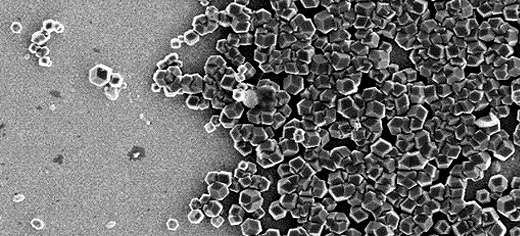
Forget computer viruses - magnet-making bacteria could be used to build tomorrow’s computers with larger hard drives and speedier connections.
Researchers at the University of Leeds have used a type of bacterium which 'eats' iron to create a surface of magnets, similar to those found in traditional hard drives, and wiring. As the bacterium ingests the iron it creates tiny magnets within itself.
The team has also begun to understand how the proteins inside these bacteria collect, shape and position these "nanomagnets" inside their cells and can now replicate this behaviour outside the bacteria.
Led by Dr Sarah Staniland from the University's School of Physics and Astronomy, in a longstanding collaboration with the Tokyo University of Agriculture and Technology, the team hope to develop a 'bottom-up' approach for creating cheaper, more environmentally-friendly electronics of the future.
Dr Staniland said: "We are quickly reaching the limits of traditional electronic manufacturing as computer components get smaller. The machines we've traditionally used to build them are clumsy at such small scales. Nature has provided us with the perfect tool to circumvent this problem."
The magnetic array was created by Leeds PhD student Johanna Galloway using a protein which creates perfect nanocrystals of magnetite inside the bacterium Magnetospirilllum magneticum. In a process akin to potato-printing on a much smaller scale, this protein is attached to a gold surface in a checkerboard pattern and placed in a solution containing iron.
At a temperature of 80°C, similarly-sized crystals of magnetite form on the sections of the surface covered by the protein. The team are now working to reduce the size of these islands of magnets, in order to make arrays of single nanomagnets. They also plan to vary the magnetic materials that this protein can control. These next steps would allow each of these nanomagnets to hold one bit of information allowing the construction of better hard drives.
"Using today's 'top-down' method - essentially sculpting tiny magnets out of a big magnet - it is increasingly difficult to produce the small magnets of the same size and shape which are needed to store data," said Johanna Galloway. "Using the method developed here at Leeds, the proteins do all the hard work; they gather the iron, create the most magnetic compound, and arrange it into regularly-sized cubes."
A different protein has been used to create tiny electrical wires by Dr Masayoshi Tanaka, during a secondment to Leeds from Tokyo University of Agriculture and Technology. These 'nanowires' are made of 'quantum dots' - particles of copper indium sulphide and zinc sulphide which glow and conduct electricity - and are encased by fat molecules, or lipids.
The magnetic bacteria contain a protein that moulds mini compartments for the nanomagnets to be formed in using the cell membrane lipids. Dr Tanaka used a similar protein to make tubes of fat containing quantum dots - biological-based wiring.
"It is possible to tune these biological wires to have a particular electrical resistance. In the future, they could be grown connected to other components as part of an entirely biological computer," said Dr Tanaka.
The research group and the team at Tokyo University of Agriculture and Technology, led by Prof. Tadashi Matsunaga, now plan to examine the biological processes behind the behaviour of these proteins. "Our aim is to develop a toolkit of proteins and chemicals which could be used to grow computer components from scratch," adds Dr Staniland.
The papers Biotemplated Magnetic Nanoparticle Arrays and Fabrication of Lipid Tubules with Embedded Quantum Dots by Membrane Tubulation Protein are published in the journal Small.
This research is funded by the Engineering and Physical Sciences Research Council (EPSRC), Biotechnology and Biological Sciences Research Council (BBSRC) and the Royal Society's Newton International Fellowships Scheme.
Source: University of Leeds
Additional Information:
May 9, 2012
Forget computer viruses - magnet-making bacteria could be used to build tomorrow’s computers with larger hard drives and speedier connections.
Researchers at the University of Leeds have used a type of bacterium which 'eats' iron to create a surface of magnets, similar to those found in traditional hard drives, and wiring. As the bacterium ingests the iron it creates tiny magnets within itself.
The team has also begun to understand how the proteins inside these bacteria collect, shape and position these "nanomagnets" inside their cells and can now replicate this behaviour outside the bacteria.
Led by Dr Sarah Staniland from the University's School of Physics and Astronomy, in a longstanding collaboration with the Tokyo University of Agriculture and Technology, the team hope to develop a 'bottom-up' approach for creating cheaper, more environmentally-friendly electronics of the future.
Dr Staniland said: "We are quickly reaching the limits of traditional electronic manufacturing as computer components get smaller. The machines we've traditionally used to build them are clumsy at such small scales. Nature has provided us with the perfect tool to circumvent this problem."
The magnetic array was created by Leeds PhD student Johanna Galloway using a protein which creates perfect nanocrystals of magnetite inside the bacterium Magnetospirilllum magneticum. In a process akin to potato-printing on a much smaller scale, this protein is attached to a gold surface in a checkerboard pattern and placed in a solution containing iron.
At a temperature of 80°C, similarly-sized crystals of magnetite form on the sections of the surface covered by the protein. The team are now working to reduce the size of these islands of magnets, in order to make arrays of single nanomagnets. They also plan to vary the magnetic materials that this protein can control. These next steps would allow each of these nanomagnets to hold one bit of information allowing the construction of better hard drives.
"Using today's 'top-down' method - essentially sculpting tiny magnets out of a big magnet - it is increasingly difficult to produce the small magnets of the same size and shape which are needed to store data," said Johanna Galloway. "Using the method developed here at Leeds, the proteins do all the hard work; they gather the iron, create the most magnetic compound, and arrange it into regularly-sized cubes."
A different protein has been used to create tiny electrical wires by Dr Masayoshi Tanaka, during a secondment to Leeds from Tokyo University of Agriculture and Technology. These 'nanowires' are made of 'quantum dots' - particles of copper indium sulphide and zinc sulphide which glow and conduct electricity - and are encased by fat molecules, or lipids.
The magnetic bacteria contain a protein that moulds mini compartments for the nanomagnets to be formed in using the cell membrane lipids. Dr Tanaka used a similar protein to make tubes of fat containing quantum dots - biological-based wiring.
"It is possible to tune these biological wires to have a particular electrical resistance. In the future, they could be grown connected to other components as part of an entirely biological computer," said Dr Tanaka.
The research group and the team at Tokyo University of Agriculture and Technology, led by Prof. Tadashi Matsunaga, now plan to examine the biological processes behind the behaviour of these proteins. "Our aim is to develop a toolkit of proteins and chemicals which could be used to grow computer components from scratch," adds Dr Staniland.
The papers Biotemplated Magnetic Nanoparticle Arrays and Fabrication of Lipid Tubules with Embedded Quantum Dots by Membrane Tubulation Protein are published in the journal Small.
This research is funded by the Engineering and Physical Sciences Research Council (EPSRC), Biotechnology and Biological Sciences Research Council (BBSRC) and the Royal Society's Newton International Fellowships Scheme.
Source: University of Leeds
Additional Information:
- Dr Sarah Staniland is available for interview. Accompanying pictures can be downloaded here:
- https://docs.google.com/open?id=0B691WmQZab8LZkptRTViSFE2UXc
- https://docs.google.com/open?id=0B691WmQZab8LUE4xOTl5cF9OX1E
- Galloway, J. M., Bramble, J. P., Rawlings, A. E., Burnell, G., Evans, S. D. and Staniland, S. S. (2012), Biotemplated Magnetic Nanoparticle Arrays. Small, 8: 204-208. (http://onlinelibrary.wiley.com/doi/10.1002/smll.201101627/abstract)
- Tanaka, M., Critchley, K., Matsunaga, T., Evans, S. D. and Staniland, S. S. (2012), Fabrication of Lipid Tubules with Embedded Quantum Dots by Membrane Tubulation Protein. Small. (http://onlinelibrary.wiley.com/doi/10.1002/smll.201102446/abstract)
Friday, 4 May 2012
Revolutionary Technology Enables Objects To Know How They Are Being Touched
Engineerblogger
May 4, 2012
A doorknob that knows whether to lock or unlock based on how it is grasped, a smartphone that silences itself if the user holds a finger to her lips and a chair that adjusts room lighting based on recognizing if a user is reclining or leaning forward are among the many possible applications of Touché, a new sensing technique developed by a team at Disney Research, Pittsburgh, and Carnegie Mellon University.
Touché is a form of capacitive touch sensing, the same principle underlying the types of touchscreens used in most smartphones. But instead of sensing electrical signals at a single frequency, like the typical touchscreen, Touché monitors capacitive signals across a broad range of frequencies.
This Swept Frequency Capacitive Sensing (SFCS) makes it possible to not only detect a "touch event," but to recognize complex configurations of the hand or body that is doing the touching. An object thus could sense how it is being touched, or might sense the body configuration of the person doing the touching.
SFCS is robust and can enhance everyday objects by using just a single sensing electrode. Sometimes, as in the case of a doorknob or other conductive objects, the object itself can serve as a sensor and no modifications are required. Even the human body or a body of water can be a sensor.
"Signal frequency sweeps have been used for decades in wireless communication, but as far as we know, nobody previously has attempted to apply this technique to touch interaction," said Ivan Poupyrev, senior research scientist at Disney Research, Pittsburgh. "Yet, in our laboratory experiments, we were able to enhance a broad variety of objects with high-fidelity touch sensitivity. When combined with gesture recognition techniques, Touché demonstrated recognition rates approaching 100 percent. That suggests it could immediately be used to create new and exciting ways for people to interact with objects and the world at large."
In addition to Poupyrev, the research team included Chris Harrison, a Ph.D. student in Carnegie Mellon's Human-Computer Interaction Institute, and Munehiko Sato, a Disney intern and a Ph.D. student in engineering at the University of Tokyo. The researchers will present their findings May 7 at CHI 2012, the Conference on Human Factors in Computing Systems, in Austin, Texas, where it has been recognized with a prestigious Best Paper Award.
Both Touché and smartphone touchscreens are based on the phenomenon known as capacitive coupling. In a capacitive touchscreen, the surface is coated with a transparent conductor that carries an electrical signal. That signal is altered when a person's finger touches it, providing an alternative path for the electrical charge. By monitoring the change in the signal, the device can determine if a touch occurs.
By monitoring a range of signal frequencies, however, Touché can derive much more information. Different body tissues have different capacitive properties, so monitoring a range of frequencies can detect a number of different paths that the electrical charge takes through the body.
Making sense of all of that SFCS information, however, requires analyzing hundreds of data points. As microprocessors have become steadily faster and less expensive, it now is feasible to use SFCS in touch interfaces, the researchers said.
"Devices keep getting smaller and increasingly are embedded throughout the environment, which has made it necessary for us to find ways to control or interact with them, and that is where Touché could really shine," Harrison said.
Sato said Touché could make computer interfaces as invisible to users as the embedded computers themselves. "This might enable us to one day do away with keyboards, mice and perhaps even conventional touchscreens for many applications," he said.
Among the proof-of-concept applications the researchers have investigated is a smart doorknob. Depending on whether the knob was grasped, touched with one finger or two, or pinched, a door could be programmed to lock or unlock itself, admit a guest, or even leave a reply message, such as "I'll be back in five minutes."
In another proof-of-concept experiment, they showed that SFCS could enhance a traditional touchscreen by sensing not just the fingertip, but the configuration of the rest of the hand. They created the equivalent of a mouse "right click," zoom in/out and copy/paste functions depending on whether the user pinched the phone's screen and back with one finger or two, or used a thumb.
The researchers also were able to monitor body gestures, such as touching fingers, grasping hands and covering ears by having subjects wear electrodes similar to wristwatches on both arms. Such gestures could be used to control a smartphone or other device.
They also showed that a single electrode attached to any water vessel could detect a number of gestures, such as fingertip submerged, hand submerged and hand on bottom. Sensing touch in liquids might be particularly suited to toys, games and food appliances.
Touché proposes a novel Swept Frequency Capacitive Sensing technique that can not only detect a touch event, but also recognize complex configurations of the human hands and body. Such contextual information significantly enhances touch interaction in a broad range of applications, from conventional touchscreens to unique contexts and materials. For example, in our explorations we add touch and gesture sensitivity to the human body and liquids. We demonstrate the rich capabilities of Touché with five example setups from different application domains and conduct experimental studies that show gesture classification accuracies of 99% are achievable with our technology.
Source: Carnegie Mellon University
Additional Information:
May 4, 2012
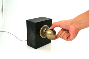 |
| Doorknob Credit: Carnegie Mellon University |
A doorknob that knows whether to lock or unlock based on how it is grasped, a smartphone that silences itself if the user holds a finger to her lips and a chair that adjusts room lighting based on recognizing if a user is reclining or leaning forward are among the many possible applications of Touché, a new sensing technique developed by a team at Disney Research, Pittsburgh, and Carnegie Mellon University.
Touché is a form of capacitive touch sensing, the same principle underlying the types of touchscreens used in most smartphones. But instead of sensing electrical signals at a single frequency, like the typical touchscreen, Touché monitors capacitive signals across a broad range of frequencies.
This Swept Frequency Capacitive Sensing (SFCS) makes it possible to not only detect a "touch event," but to recognize complex configurations of the hand or body that is doing the touching. An object thus could sense how it is being touched, or might sense the body configuration of the person doing the touching.
SFCS is robust and can enhance everyday objects by using just a single sensing electrode. Sometimes, as in the case of a doorknob or other conductive objects, the object itself can serve as a sensor and no modifications are required. Even the human body or a body of water can be a sensor.
"Signal frequency sweeps have been used for decades in wireless communication, but as far as we know, nobody previously has attempted to apply this technique to touch interaction," said Ivan Poupyrev, senior research scientist at Disney Research, Pittsburgh. "Yet, in our laboratory experiments, we were able to enhance a broad variety of objects with high-fidelity touch sensitivity. When combined with gesture recognition techniques, Touché demonstrated recognition rates approaching 100 percent. That suggests it could immediately be used to create new and exciting ways for people to interact with objects and the world at large."
In addition to Poupyrev, the research team included Chris Harrison, a Ph.D. student in Carnegie Mellon's Human-Computer Interaction Institute, and Munehiko Sato, a Disney intern and a Ph.D. student in engineering at the University of Tokyo. The researchers will present their findings May 7 at CHI 2012, the Conference on Human Factors in Computing Systems, in Austin, Texas, where it has been recognized with a prestigious Best Paper Award.
Both Touché and smartphone touchscreens are based on the phenomenon known as capacitive coupling. In a capacitive touchscreen, the surface is coated with a transparent conductor that carries an electrical signal. That signal is altered when a person's finger touches it, providing an alternative path for the electrical charge. By monitoring the change in the signal, the device can determine if a touch occurs.
By monitoring a range of signal frequencies, however, Touché can derive much more information. Different body tissues have different capacitive properties, so monitoring a range of frequencies can detect a number of different paths that the electrical charge takes through the body.
Making sense of all of that SFCS information, however, requires analyzing hundreds of data points. As microprocessors have become steadily faster and less expensive, it now is feasible to use SFCS in touch interfaces, the researchers said.
"Devices keep getting smaller and increasingly are embedded throughout the environment, which has made it necessary for us to find ways to control or interact with them, and that is where Touché could really shine," Harrison said.
Sato said Touché could make computer interfaces as invisible to users as the embedded computers themselves. "This might enable us to one day do away with keyboards, mice and perhaps even conventional touchscreens for many applications," he said.
Among the proof-of-concept applications the researchers have investigated is a smart doorknob. Depending on whether the knob was grasped, touched with one finger or two, or pinched, a door could be programmed to lock or unlock itself, admit a guest, or even leave a reply message, such as "I'll be back in five minutes."
In another proof-of-concept experiment, they showed that SFCS could enhance a traditional touchscreen by sensing not just the fingertip, but the configuration of the rest of the hand. They created the equivalent of a mouse "right click," zoom in/out and copy/paste functions depending on whether the user pinched the phone's screen and back with one finger or two, or used a thumb.
The researchers also were able to monitor body gestures, such as touching fingers, grasping hands and covering ears by having subjects wear electrodes similar to wristwatches on both arms. Such gestures could be used to control a smartphone or other device.
They also showed that a single electrode attached to any water vessel could detect a number of gestures, such as fingertip submerged, hand submerged and hand on bottom. Sensing touch in liquids might be particularly suited to toys, games and food appliances.
Touché proposes a novel Swept Frequency Capacitive Sensing technique that can not only detect a touch event, but also recognize complex configurations of the human hands and body. Such contextual information significantly enhances touch interaction in a broad range of applications, from conventional touchscreens to unique contexts and materials. For example, in our explorations we add touch and gesture sensitivity to the human body and liquids. We demonstrate the rich capabilities of Touché with five example setups from different application domains and conduct experimental studies that show gesture classification accuracies of 99% are achievable with our technology.
Source: Carnegie Mellon University
Additional Information:
- Touché can be found at: http://www.disneyresearch.com/research/human_comp_interaction.htm
Thursday, 3 May 2012
Printed loudspeakers: Paper with good sound quality
Engineerblogger
May 3, 2012
At drupa print media fair, the Institute for Print and Media Technology of Chemnitz University of Technology presents printed loudspeakers on paper substrate and a solar tree with printed solar cells.
At drupa, the world’s largest fair on print media technology, which takes place from 3 to 16 May 2012 in Düsseldorf, the Institute for Print and Media Technology of Chemnitz University of Technology (pmTUC) presents new research results, which truly make you prick up your ears: Loudspeakers that have been printed with flexography on standard paper. The R&D group of Prof. Dr. Arved Hübler, head of pmTUC, is co-exhibitor of press manufacturer Windmöller & Hölscher KG (Lengerich) and can be found in hall 15, booth A41/1.
The printed paper loudspeaker is connected to an audio amplifier like a conventional loudspeaker. "Frequency response and hence sound quality are very good and the paper is surprisingly loud. Just the bass of the paper-based loudspeaker is a bit weak”, explains Dr. Georg Schmidt, senior researcher at pmTUC. The thin loudspeakers, which are printed in the laboratories of pmTUC, contain several layers of a conductive organic polymer and a piezoactive layer. According to project assistant Maxi Bellmann the loudspeakers are astonishingly robust and can be produced in a very cheap way as mass printing methods are used. The bottom side of the paper loudspeaker provides unused space on which coloured messages can be printed.
Prof. Hübler expects a broad range of new applications: The paper loudspeakers could, for instance, be integrated into common print products. As such, they offer an enormous potential for the advertising segment. "In addition, sound wallpapers and purely technical applications, e.g., distance sensors, are possible, because the papers are also active in the ultrasound range”, says Hübler and adds: "As printing allows for different formats and forms, there is the possibility to influence the generated sound waves.” The loudspeaker of pmTUC was realised within the framework of the project Plastic Acoustics (PACU), which is funded by the Federal Ministry of Education and Research and includes the following project partners: Robert Bosch GmbH (Stuttgart), Heraeus Clevios GmbH (Leverkusen), X-Spex GmbH (Berlin), and Fraunhofer Institute for Electronic Nano Systems ENAS (Chemnitz).
Electricity that grows on trees
Besides printed loudspeakers, pmTUC presents innovative application scenarios for printed solar cells. "Half a year ago, we introduced the world’s first 3PV technology - printed paper photovoltaics, says Hübler. At drupa, the Chemnitz researchers exhibit a solar tree with 50 printed solar leaves. Similar to an ordinary tree, the leaves that face the sun collect energy. They are connected with snap fasteners. Via a cable in the hollow tree trunk the solar electricity supplies a battery.
"If you stand below the tree and look up to the shade-giving leaves of the solar tree, you can see that the bottom side of the leaves is printed with advertisements”, explains Hübler and adds with a twinkle in his eye: "That’s even better than in nature.” Because according to Hübler, the advertising segment is the driving force of the printing industry: "As soon as the customer realises that it is better to not throw advertising that contains a solar cell away, but rather keep it to generate electricity for some time, the printed solar cell will become an unbeatable advertising carrier with a sustainable image”, reports the professor from Chemnitz. Hübler does not only believe that the 3PV technology, developed at Chemnitz University of Technology, will make a contribution to global power supplies in the future, but also that 3PV will bring about the breakthrough of printed electronics.
In his book "print becomes electronics”, which is published in English and German on occasion of drupa, Hübler analyses the backgrounds of this development and explains the transition that he expects to take place in the traditional graphic arts industry. According to Hübler, electronic media and conventional print media will increasingly merge in the future: "A large part of electronics will be printed, and most print media will be electronic.” The book is available at drupa and upon request from pmTUC.
Source: Chemnitz University of Technology
May 3, 2012
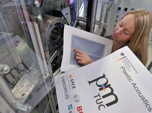 |
| Maxi Bellmann, researcher at the Institute for Print and Media Technology of Chemnitz University of Technology, shows the printed loudspeaker area. The bottom side of the paper loudspeaker can be printed with advertising messages - in this case you can see the logos of the project partners. Photo: Hendrik Schmidt. |
At drupa print media fair, the Institute for Print and Media Technology of Chemnitz University of Technology presents printed loudspeakers on paper substrate and a solar tree with printed solar cells.
At drupa, the world’s largest fair on print media technology, which takes place from 3 to 16 May 2012 in Düsseldorf, the Institute for Print and Media Technology of Chemnitz University of Technology (pmTUC) presents new research results, which truly make you prick up your ears: Loudspeakers that have been printed with flexography on standard paper. The R&D group of Prof. Dr. Arved Hübler, head of pmTUC, is co-exhibitor of press manufacturer Windmöller & Hölscher KG (Lengerich) and can be found in hall 15, booth A41/1.
The printed paper loudspeaker is connected to an audio amplifier like a conventional loudspeaker. "Frequency response and hence sound quality are very good and the paper is surprisingly loud. Just the bass of the paper-based loudspeaker is a bit weak”, explains Dr. Georg Schmidt, senior researcher at pmTUC. The thin loudspeakers, which are printed in the laboratories of pmTUC, contain several layers of a conductive organic polymer and a piezoactive layer. According to project assistant Maxi Bellmann the loudspeakers are astonishingly robust and can be produced in a very cheap way as mass printing methods are used. The bottom side of the paper loudspeaker provides unused space on which coloured messages can be printed.
Prof. Hübler expects a broad range of new applications: The paper loudspeakers could, for instance, be integrated into common print products. As such, they offer an enormous potential for the advertising segment. "In addition, sound wallpapers and purely technical applications, e.g., distance sensors, are possible, because the papers are also active in the ultrasound range”, says Hübler and adds: "As printing allows for different formats and forms, there is the possibility to influence the generated sound waves.” The loudspeaker of pmTUC was realised within the framework of the project Plastic Acoustics (PACU), which is funded by the Federal Ministry of Education and Research and includes the following project partners: Robert Bosch GmbH (Stuttgart), Heraeus Clevios GmbH (Leverkusen), X-Spex GmbH (Berlin), and Fraunhofer Institute for Electronic Nano Systems ENAS (Chemnitz).
Electricity that grows on trees
Besides printed loudspeakers, pmTUC presents innovative application scenarios for printed solar cells. "Half a year ago, we introduced the world’s first 3PV technology - printed paper photovoltaics, says Hübler. At drupa, the Chemnitz researchers exhibit a solar tree with 50 printed solar leaves. Similar to an ordinary tree, the leaves that face the sun collect energy. They are connected with snap fasteners. Via a cable in the hollow tree trunk the solar electricity supplies a battery.
"If you stand below the tree and look up to the shade-giving leaves of the solar tree, you can see that the bottom side of the leaves is printed with advertisements”, explains Hübler and adds with a twinkle in his eye: "That’s even better than in nature.” Because according to Hübler, the advertising segment is the driving force of the printing industry: "As soon as the customer realises that it is better to not throw advertising that contains a solar cell away, but rather keep it to generate electricity for some time, the printed solar cell will become an unbeatable advertising carrier with a sustainable image”, reports the professor from Chemnitz. Hübler does not only believe that the 3PV technology, developed at Chemnitz University of Technology, will make a contribution to global power supplies in the future, but also that 3PV will bring about the breakthrough of printed electronics.
In his book "print becomes electronics”, which is published in English and German on occasion of drupa, Hübler analyses the backgrounds of this development and explains the transition that he expects to take place in the traditional graphic arts industry. According to Hübler, electronic media and conventional print media will increasingly merge in the future: "A large part of electronics will be printed, and most print media will be electronic.” The book is available at drupa and upon request from pmTUC.
Source: Chemnitz University of Technology
Wednesday, 2 May 2012
Robotics: Flying 3D eye-bots
Engineerblogger
May 2, 2012
They can be deployed as additional surveillance resources during major events, or as high-resolution 3D street imaging systems. Intelligent swarms of aerial drones are a universally useful tool for police, crisis managers and urban planners. Special 3D sensors developed by Fraunhofer researchers ensure flawless aerobatics and prevent collisions.
Like a well-rehearsed formation team, a flock of flying robots rises slowly into the air with a loud buzzing noise. A good two dozen in number, they perform an intricate dance in the sky above the seething hordes of soccer fans. Rowdy hooligans have stormed the field and set off flares. Fights are breaking out all over, smoke is hindering visibility, and chaos is the order of the day. Only the swarm of flying drones can maintain an overview of the situation. These unmanned aerial vehicles (UAVs) are a kind of mini-helicopter, with a wingspan of around two meters. They have a propeller on each of their two variable-geometry side wings, which lends them rapid and precise maneuverability. In operation over the playing field, their cameras and sensors capture urgently-needed images and data, and transmit them to the control center. Where are the most seriously injured people? What’s the best way to separate the rival gangs? The information provided by the drones allows the head of operations to make important decions more quickly, while the robots form up to go about their business above the arena autonomously – and without ever colliding with each other, or with any other obstacles.
A CMOS sensor developed by researchers at the Fraunhofer Institute for Microelectronic Circuits and Systems IMS in Duisburg lies at the heart of the anti-collision technology. “The sensor can measure three-dimensional distances very efficiently,” says Werner Brockherde, head of the development department. Just as in a black and white camera, every pixel on the sensor is given a gray value. “But on top of that,” he explains, “each pixel is also assigned a distance value.” This enables the drones to accurately determine their position in relation to other objects around them.
Sensor has a higher resolution than radar
The distance sensor developed by the IMS offers significant advantages over radar, which measures distances using reflected echoes. “The sensor has a much higher local resolution,” says Brockherde. “Given the near-field operating conditions, radar images would be far too coarse.” The flying robots are capable of identifying even small objects measuring 20 by 15 centimeters at ranges of up to 7.5 meters. Moreover, this distance information is then transmitted at the very impressive rate of 12 images per second.
Even when there is interfering light, for example when a drone is flying directly into the sun, the sensor will deliver accurate images. It operates according to the time-of-flight (TOF) process, whereby light sources emit short pulses that are reflected by objects and bounced back to the sensor. In order to prevent over-bright ambient light from masking the signal, the electronic shutter only opens for a few nanoseconds. In addition, the sensor also takes differential measurements, in which the first image is captured using ambient light only, a second is taken using the light pulse as well, and the difference between the two determines the required output signal. “All of this happens in real time,” adds Brockherde.
The 3D distance sensors are built into cameras manufactured by TriDiCam, a spin-off company of Fraunhofer IMS. Jochen Noell, TriDiCam’s managing director, admits: “This research project has presented us with new challenges as regards ambient operating conditions and the safety of the sensor technology.” The work falls under the AVIGLE project, one of the winners of the ‘Hightech.NRW’ cutting-edge technology competition which receives funding from both the Land of North Rhine-Westphalia and the EU. The IMS engineers will be presenting their sensor technology at the Fraunhofer CMOS Imaging Workshop in Duisburg on June 12 and 13 this year.
Conducting intelligent aerial surveillance of major events is not the only intended use for flying robots. They could also be of benefit to disaster relief workers, and likewise to urban planners, who could utilize them to produce detailed 3D models of streets or to inspect roofs in order to establish their suitability for solar installations. Whether deployed to create virtual maps of difficult-to-access areas, to monitor construction sites or to measure contamination at nuclear power plants, these mini UAVs could potentially be used in a wide range of applications, obviating the need for expensive aerial photography and/or satellite imaging.
Source: Fraunhofer-Gesellschaft
May 2, 2012
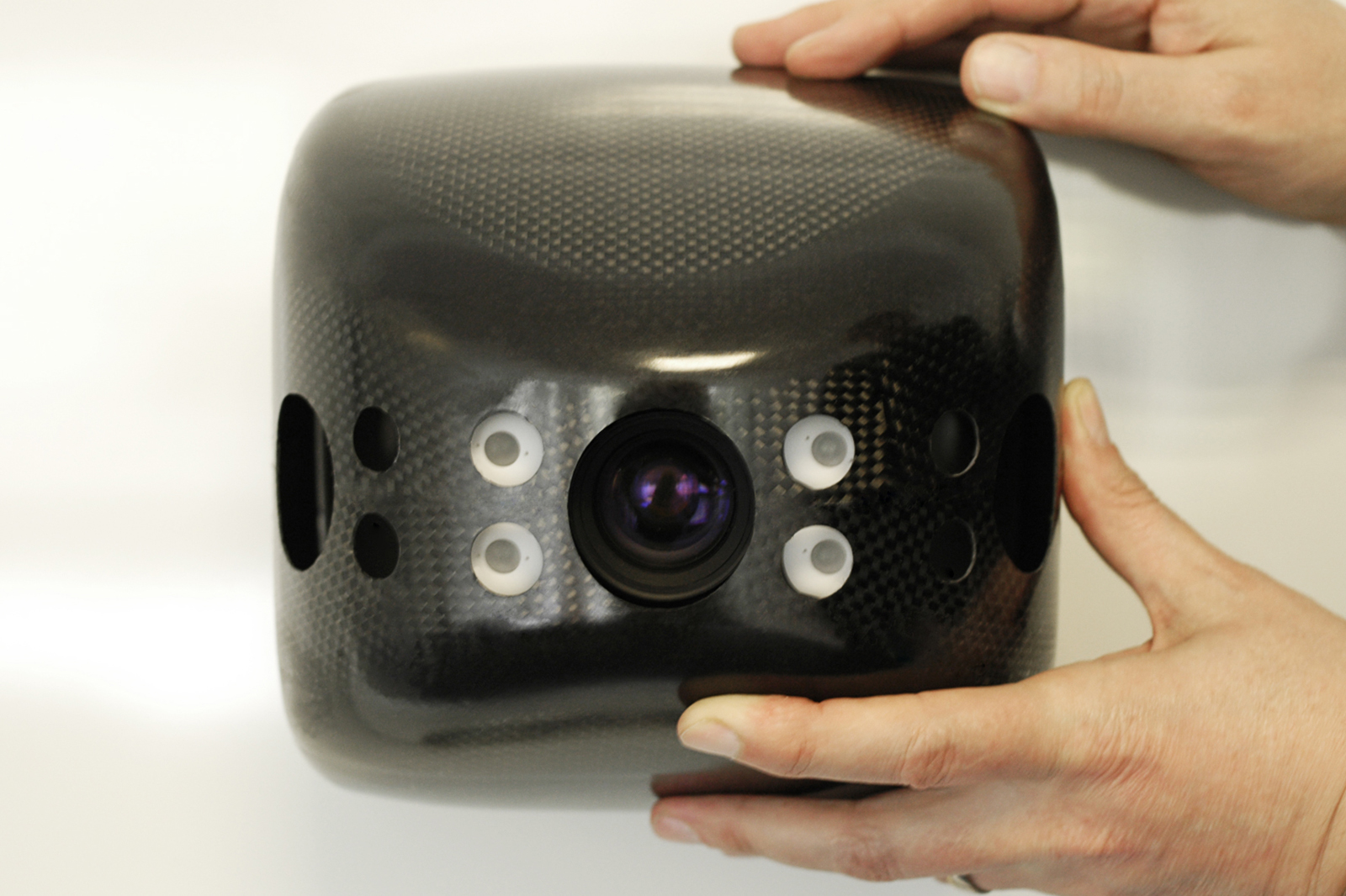 |
| The 3D camera in the flying robot can identify small objects measuring 20 by 15 centimeters from seven meters away. © Fraunhofer IMS |
They can be deployed as additional surveillance resources during major events, or as high-resolution 3D street imaging systems. Intelligent swarms of aerial drones are a universally useful tool for police, crisis managers and urban planners. Special 3D sensors developed by Fraunhofer researchers ensure flawless aerobatics and prevent collisions.
Like a well-rehearsed formation team, a flock of flying robots rises slowly into the air with a loud buzzing noise. A good two dozen in number, they perform an intricate dance in the sky above the seething hordes of soccer fans. Rowdy hooligans have stormed the field and set off flares. Fights are breaking out all over, smoke is hindering visibility, and chaos is the order of the day. Only the swarm of flying drones can maintain an overview of the situation. These unmanned aerial vehicles (UAVs) are a kind of mini-helicopter, with a wingspan of around two meters. They have a propeller on each of their two variable-geometry side wings, which lends them rapid and precise maneuverability. In operation over the playing field, their cameras and sensors capture urgently-needed images and data, and transmit them to the control center. Where are the most seriously injured people? What’s the best way to separate the rival gangs? The information provided by the drones allows the head of operations to make important decions more quickly, while the robots form up to go about their business above the arena autonomously – and without ever colliding with each other, or with any other obstacles.
A CMOS sensor developed by researchers at the Fraunhofer Institute for Microelectronic Circuits and Systems IMS in Duisburg lies at the heart of the anti-collision technology. “The sensor can measure three-dimensional distances very efficiently,” says Werner Brockherde, head of the development department. Just as in a black and white camera, every pixel on the sensor is given a gray value. “But on top of that,” he explains, “each pixel is also assigned a distance value.” This enables the drones to accurately determine their position in relation to other objects around them.
Sensor has a higher resolution than radar
The distance sensor developed by the IMS offers significant advantages over radar, which measures distances using reflected echoes. “The sensor has a much higher local resolution,” says Brockherde. “Given the near-field operating conditions, radar images would be far too coarse.” The flying robots are capable of identifying even small objects measuring 20 by 15 centimeters at ranges of up to 7.5 meters. Moreover, this distance information is then transmitted at the very impressive rate of 12 images per second.
Even when there is interfering light, for example when a drone is flying directly into the sun, the sensor will deliver accurate images. It operates according to the time-of-flight (TOF) process, whereby light sources emit short pulses that are reflected by objects and bounced back to the sensor. In order to prevent over-bright ambient light from masking the signal, the electronic shutter only opens for a few nanoseconds. In addition, the sensor also takes differential measurements, in which the first image is captured using ambient light only, a second is taken using the light pulse as well, and the difference between the two determines the required output signal. “All of this happens in real time,” adds Brockherde.
The 3D distance sensors are built into cameras manufactured by TriDiCam, a spin-off company of Fraunhofer IMS. Jochen Noell, TriDiCam’s managing director, admits: “This research project has presented us with new challenges as regards ambient operating conditions and the safety of the sensor technology.” The work falls under the AVIGLE project, one of the winners of the ‘Hightech.NRW’ cutting-edge technology competition which receives funding from both the Land of North Rhine-Westphalia and the EU. The IMS engineers will be presenting their sensor technology at the Fraunhofer CMOS Imaging Workshop in Duisburg on June 12 and 13 this year.
Conducting intelligent aerial surveillance of major events is not the only intended use for flying robots. They could also be of benefit to disaster relief workers, and likewise to urban planners, who could utilize them to produce detailed 3D models of streets or to inspect roofs in order to establish their suitability for solar installations. Whether deployed to create virtual maps of difficult-to-access areas, to monitor construction sites or to measure contamination at nuclear power plants, these mini UAVs could potentially be used in a wide range of applications, obviating the need for expensive aerial photography and/or satellite imaging.
Source: Fraunhofer-Gesellschaft
Medical: Hip implant for long-term use
Engineerblogger
May 2, 2012
Hip replacement is one of the most frequent operations carried out in Germany. Each year, doctors implant some 200,000 artificial hip joints. Often the artificial hips need to be replaced just ten years later. In the future, a new implant currently being developed using high technology materials could help prevent premature revision surgeries.
Thanks to artificial hips, people with irreparable damage to the joint have been able to lead active, pain-free lives for the past 50 years. Still, some hip replacements do not function completely as intended, and metal-on-metal implants in particular, demand accurate positioning in surgery and implants positioned non optimally are often susceptible to premature failure notably in small female patients. Physicians are even calling for a prohibition on the use of artificial joints made of cobalt-chromium alloys in which the joint‘s metal ball rubs against its metal socket whenever the wearer walks. Poorly designed or positioned metal on metal implants can lead to higher wear rates and this releases elevated cobalt-chromium ion levels that spread out through the blood and lymph, potentially damaging organs and triggering inflammation. Metal ions are also suspected carcinogens. Because these hip replacements are so robust, however, to date they have often been implanted in young, active patients.
A metal-free composite
Researchers at the Fraunhofer Institute for Manufacturing Engineering and Automation IPA in Stuttgart, partnering in an international team on an EC-funded project entitled “ENDURE” (Enhanced Durability Resurfacing Endoprosthesis), have now developed a new kind of hip implant that, unlike the conventional counterpart implants on the market today, provide a metal-free solution and bone-like elasticity. This is the result of a metal-free, high-tech composite: The hip socket is made of carbon fibre-reinforced PEEK – a high-strength, wear resistant, biocompatible polymer composite. For the femoral head, ceramic was used. In addition to this, a hydroxylapatite coating at the interface to the bone helps ensure that the bone tissue will fuse thoroughly with the surface structure of the implant. “The cobalt-chromium implants in use to date are very rigid, and the load transfer to the bone is non-optimal leading to potential adverse bone adaptation. Thanks to the new combination of materials, the transmission of force through the PEEK hip socket to the pelvic bone is modeled on natural conditions. And there are no metal ions released,“ notes IPA engineer Jasmin Hipp. The researcher and her team were able to confirm the good wear resistance in initial tests of the new hip replacement using a robot that simulated various series of movements such as walking or climbing and descending stairs. The experiments used a prototype of the implant.
Tiny pins protect bone tissue
The ENDURE implants follow the bone-preserving principle of hip resurfacing: they are thin-walled shells which replace the bearing surface of the joint articulation alone, instead of employing large metal stems for support, which require a substantial volume of bone to be removed. Researchers have also redesigned the way the prosthesis is mechanically attached to the bone. Without cement, and using a press-fit and an integral scaffold-type structure on the surfaces of the implant that contact the bone, the hemispherical ball and socket are tapped onto the prepared femoral head and into the acetabulum – the natural, concave surface of the pelvis – and anchored in place.
To ensure the best possible positioning of the artificial hip, the researchers at IPA have developed a size-scalable tool that attaches the implant to standard surgical instruments, enabling implantation, re-alignment and removal. The tool can be discarded after a single use – like a disposable surgical glove. The challenge is to attach instruments to the very thin-walled cup implant, with sufficient strength for implant repositioning. The instrument features a smart collet pin combination allowing strong, quick, single-position attachment and detachment by the surgeon. The scientists have already submitted a patent application for the tool. A team of physicians at the University of Newcastle have demonstrated in operations performed on cadavers, the new hip can be set in place and, if necessary, removed without any difficulties. Meanwhile, the preclinical studies have been completed, and final development work is being planned to allow clinical studies to commence. Partners in the EU-funded project are Aurora Medical, Medicoat, Hunt Developments, Ala Ortho, CeramTec, Invibio, Biomatech and the Universities of Gothenburg and Southampton.
Source: Fraunhofer-Gesellschaft
May 2, 2012
 |
| The ceramic femoral head fits perfectly into the PEEK hip socket. © Fraunhofer IPA |
Hip replacement is one of the most frequent operations carried out in Germany. Each year, doctors implant some 200,000 artificial hip joints. Often the artificial hips need to be replaced just ten years later. In the future, a new implant currently being developed using high technology materials could help prevent premature revision surgeries.
Thanks to artificial hips, people with irreparable damage to the joint have been able to lead active, pain-free lives for the past 50 years. Still, some hip replacements do not function completely as intended, and metal-on-metal implants in particular, demand accurate positioning in surgery and implants positioned non optimally are often susceptible to premature failure notably in small female patients. Physicians are even calling for a prohibition on the use of artificial joints made of cobalt-chromium alloys in which the joint‘s metal ball rubs against its metal socket whenever the wearer walks. Poorly designed or positioned metal on metal implants can lead to higher wear rates and this releases elevated cobalt-chromium ion levels that spread out through the blood and lymph, potentially damaging organs and triggering inflammation. Metal ions are also suspected carcinogens. Because these hip replacements are so robust, however, to date they have often been implanted in young, active patients.
A metal-free composite
Researchers at the Fraunhofer Institute for Manufacturing Engineering and Automation IPA in Stuttgart, partnering in an international team on an EC-funded project entitled “ENDURE” (Enhanced Durability Resurfacing Endoprosthesis), have now developed a new kind of hip implant that, unlike the conventional counterpart implants on the market today, provide a metal-free solution and bone-like elasticity. This is the result of a metal-free, high-tech composite: The hip socket is made of carbon fibre-reinforced PEEK – a high-strength, wear resistant, biocompatible polymer composite. For the femoral head, ceramic was used. In addition to this, a hydroxylapatite coating at the interface to the bone helps ensure that the bone tissue will fuse thoroughly with the surface structure of the implant. “The cobalt-chromium implants in use to date are very rigid, and the load transfer to the bone is non-optimal leading to potential adverse bone adaptation. Thanks to the new combination of materials, the transmission of force through the PEEK hip socket to the pelvic bone is modeled on natural conditions. And there are no metal ions released,“ notes IPA engineer Jasmin Hipp. The researcher and her team were able to confirm the good wear resistance in initial tests of the new hip replacement using a robot that simulated various series of movements such as walking or climbing and descending stairs. The experiments used a prototype of the implant.
Tiny pins protect bone tissue
The ENDURE implants follow the bone-preserving principle of hip resurfacing: they are thin-walled shells which replace the bearing surface of the joint articulation alone, instead of employing large metal stems for support, which require a substantial volume of bone to be removed. Researchers have also redesigned the way the prosthesis is mechanically attached to the bone. Without cement, and using a press-fit and an integral scaffold-type structure on the surfaces of the implant that contact the bone, the hemispherical ball and socket are tapped onto the prepared femoral head and into the acetabulum – the natural, concave surface of the pelvis – and anchored in place.
To ensure the best possible positioning of the artificial hip, the researchers at IPA have developed a size-scalable tool that attaches the implant to standard surgical instruments, enabling implantation, re-alignment and removal. The tool can be discarded after a single use – like a disposable surgical glove. The challenge is to attach instruments to the very thin-walled cup implant, with sufficient strength for implant repositioning. The instrument features a smart collet pin combination allowing strong, quick, single-position attachment and detachment by the surgeon. The scientists have already submitted a patent application for the tool. A team of physicians at the University of Newcastle have demonstrated in operations performed on cadavers, the new hip can be set in place and, if necessary, removed without any difficulties. Meanwhile, the preclinical studies have been completed, and final development work is being planned to allow clinical studies to commence. Partners in the EU-funded project are Aurora Medical, Medicoat, Hunt Developments, Ala Ortho, CeramTec, Invibio, Biomatech and the Universities of Gothenburg and Southampton.
Source: Fraunhofer-Gesellschaft
Friday, 27 April 2012
Manufacturing: Assembly errors quickly identified
Engineerblogger
April 27, 2012
If errors creep in during the assembly of components, costly post-processing is often the consequence. Automatic testing is difficult, especially where individual products are concerned. Now there is a new testing system that is flexible and economical, even for smaller production runs. Researchers will be presenting the new technology at the Control trade fair, May 8-11 in Stuttgart.
Today‘s cars are increasingly custom-built. One customer might want electric windows, heated door mirrors and steering-wheel-mounted stereo controls, while another is satisfied with the minimum basic equipment. The situation with aircraft is no different: each airline is looking for different interior finishes – and lighting, ventilation, seating and monitors are different from one company to the next. Yet the customer‘s freedom is the manufacturer‘s challenge: because individual parts and mountings have to be installed in different locations along the fuselage, automated assembly is often not an economical alternative. For many assembly steps, manufacturers have to rely on manual labor instead. But if errors creep in – if, for instance, a bracket is mounted backwards or in the wrong place – correcting them can get expensive later on. The fuselage has to be reworked at great expense. Today, employees use design drawings to determine whether the individual parts have been attached properly, or else manufacturers use rigid and inflexible testing systems to check the part against comparison photos. This calls for an identical part for the template photo – and that can be difficult where one-off parts are concerned.
Now, researchers at the Fraunhofer Institute for Factory Operation and Automation IFF in Magdeburg have come up with a testing technology that is reliable and economic even for one-off production runs. “The automated visual testing system generates a digital template and uses it to compare with the assembled components. It reliably identifies any errors,“ points out Steffen Sauer, project manager for measuring and testing technology at IFF. First, an automated camera system takes hundreds of photos of individually assembled holders, load-bearing elements and parts on the inside of the fuselage shell. For every picture taken, the system determines the exact position of the camera relative to the fuselage shell. At the same time, the software generates the same shots again – but this time using a “virtual“ camera. So essentially it creates “photos“ using the data of the digital design model. The system compares the photos of real parts with the “virtual“ images. If the system detects any deviations – if, say, a bracket is backwards – it issues a warning. Parts that have not been installed properly are highlighted on the monitor screen. The interesting thing is these steps are completely automatic.
In addition to a two-dimensional check using the photos, the system can also check a completed aircraft fuselage in three dimension: as in the case of the photos, it uses design data to generate three-dimensional data that it then compares with measurements on the real assembly. Here, conventional 3D measurement methods are used to digitalize the components. “What‘s new about this system is that we convert specifications from the design models into images and 3D data that the system can then compare with the real images,“ explains Sauer.. The system also automatically draws up the testing plan: first, it identifies the best measuring position for every part to be tested. What is the best location from which to test the component in question? The system forwards the results to the robot, which in turn travels to the position identified, where it shoots the two or three-dimensional images. There is another advantage to this approach: this way, the system can react quickly and flexibly. The result is a continuous process, from design to the finished and assembled part.
The main challenge to researchers was to set up the virtual camera that uses design models to “photograph“ the as yet non-existent component. Another crunch point was to quickly and automatically locate the interesting areas from among the many millions of points in the three-dimensional images – to hunt down, in the mass of points, the tiny components such as brackets and holders, and to check to see whether they are properly fitted. The fields of application for this testing technology are diverse: the technology can be used wherever flexibility is required and individual parts frequently change. The only condition: design data must be available. Researchers will be presenting the new technology at the Control trade fair, May 8-11 in Stuttgart. The process will be ready to use by summer 2012.
Source: Fraunhofer-Gesellschaft
April 27, 2012
 |
| Parts that have not been installed properly are highlighted on the monitor screen. © Fraunhofer IF |
If errors creep in during the assembly of components, costly post-processing is often the consequence. Automatic testing is difficult, especially where individual products are concerned. Now there is a new testing system that is flexible and economical, even for smaller production runs. Researchers will be presenting the new technology at the Control trade fair, May 8-11 in Stuttgart.
Today‘s cars are increasingly custom-built. One customer might want electric windows, heated door mirrors and steering-wheel-mounted stereo controls, while another is satisfied with the minimum basic equipment. The situation with aircraft is no different: each airline is looking for different interior finishes – and lighting, ventilation, seating and monitors are different from one company to the next. Yet the customer‘s freedom is the manufacturer‘s challenge: because individual parts and mountings have to be installed in different locations along the fuselage, automated assembly is often not an economical alternative. For many assembly steps, manufacturers have to rely on manual labor instead. But if errors creep in – if, for instance, a bracket is mounted backwards or in the wrong place – correcting them can get expensive later on. The fuselage has to be reworked at great expense. Today, employees use design drawings to determine whether the individual parts have been attached properly, or else manufacturers use rigid and inflexible testing systems to check the part against comparison photos. This calls for an identical part for the template photo – and that can be difficult where one-off parts are concerned.
Now, researchers at the Fraunhofer Institute for Factory Operation and Automation IFF in Magdeburg have come up with a testing technology that is reliable and economic even for one-off production runs. “The automated visual testing system generates a digital template and uses it to compare with the assembled components. It reliably identifies any errors,“ points out Steffen Sauer, project manager for measuring and testing technology at IFF. First, an automated camera system takes hundreds of photos of individually assembled holders, load-bearing elements and parts on the inside of the fuselage shell. For every picture taken, the system determines the exact position of the camera relative to the fuselage shell. At the same time, the software generates the same shots again – but this time using a “virtual“ camera. So essentially it creates “photos“ using the data of the digital design model. The system compares the photos of real parts with the “virtual“ images. If the system detects any deviations – if, say, a bracket is backwards – it issues a warning. Parts that have not been installed properly are highlighted on the monitor screen. The interesting thing is these steps are completely automatic.
In addition to a two-dimensional check using the photos, the system can also check a completed aircraft fuselage in three dimension: as in the case of the photos, it uses design data to generate three-dimensional data that it then compares with measurements on the real assembly. Here, conventional 3D measurement methods are used to digitalize the components. “What‘s new about this system is that we convert specifications from the design models into images and 3D data that the system can then compare with the real images,“ explains Sauer.. The system also automatically draws up the testing plan: first, it identifies the best measuring position for every part to be tested. What is the best location from which to test the component in question? The system forwards the results to the robot, which in turn travels to the position identified, where it shoots the two or three-dimensional images. There is another advantage to this approach: this way, the system can react quickly and flexibly. The result is a continuous process, from design to the finished and assembled part.
The main challenge to researchers was to set up the virtual camera that uses design models to “photograph“ the as yet non-existent component. Another crunch point was to quickly and automatically locate the interesting areas from among the many millions of points in the three-dimensional images – to hunt down, in the mass of points, the tiny components such as brackets and holders, and to check to see whether they are properly fitted. The fields of application for this testing technology are diverse: the technology can be used wherever flexibility is required and individual parts frequently change. The only condition: design data must be available. Researchers will be presenting the new technology at the Control trade fair, May 8-11 in Stuttgart. The process will be ready to use by summer 2012.
Source: Fraunhofer-Gesellschaft
Subscribe to:
Posts (Atom)