Blogger Themes

Showing posts with label United States. Show all posts

Friday, 15 February 2013

Forget about leprechauns, engineers are catching rainbows

Engineerblogger
Feb 15, 2012

An image of the “hyperbolic metamaterial waveguide,” which catches an ultimately absorbs wavelengths (or color) in a vertical direction.
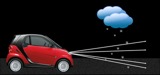
An up-close look at the “hyperbolic metamaterial waveguide,” which catches and ultimately absorbs wavelengths (or color) in a vertical direction.


University at Buffalo engineers have created a more efficient way to catch rainbows, an advancement in photonics that could lead to technological breakthroughs in solar energy, stealth technology and other areas of research.

Qiaoqiang Gan, PhD, an assistant professor of electrical engineering at UB, and a team of graduate students described their work in a paper called “Rainbow Trapping in Hyperbolic Metamaterial Waveguide,” published in the online journal Scientific Reports.

They developed a “hyperbolic metamaterial waveguide,” which is essentially an advanced microchip made of alternate ultra-thin films of metal and semiconductors and/or insulators. The waveguide halts and ultimately absorbs each frequency of light, at slightly different places in a vertical direction (see the above figure), to catch a “rainbow” of wavelengths.

Gan is a researcher within UB’s new Center of Excellence in Materials Informatics.

“Electromagnetic absorbers have been studied for many years, especially for military radar systems,” Gan said. “Right now, researchers are developing compact light absorbers based on optically thick semiconductors or carbon nanotubes. However, it is still challenging to realize the perfect absorber in ultra-thin films with tunable absorption band.

“We are developing ultra-thin films that will slow the light and therefore allow much more efficient absorption, which will address the long existing challenge.”

Light is made of photons that, because they move extremely fast (i.e., at the speed of light), are difficult to tame. In their initial attempts to slow light, researchers relied upon cryogenic gases. But because cryogenic gases are very cold – roughly 240 degrees below zero Fahrenheit – they are difficult to work with outside a laboratory.

Before joining UB, Gan helped pioneer a way to slow light without cryogenic gases. He and other researchers at Lehigh University made nano-scale-sized grooves in metallic surfaces at different depths, a process that altered the optical properties of the metal. While the grooves worked, they had limitations. For example, the energy of the incident light cannot be transferred onto the metal surface efficiently, which hampered its use for practical applications, Gan said.

The hyperbolic metamaterial waveguide solves that problem because it is a large area of patterned film that can collect the incident light efficiently. It is referred to as an artificial medium with subwavelength features whose frequency surface is hyperboloid, which allows it to capture a wide range of wavelengths in different frequencies including visible, near-infrared, mid-infrared, terahertz and microwaves.

It could lead to advancements in an array of fields.

For example, in electronics there is a phenomenon known as crosstalk, in which a signal transmitted on one circuit or channel creates an undesired effect in another circuit or channel. The on-chip absorber could potentially prevent this.

The on-chip absorber may also be applied to solar panels and other energy-harvesting devices. It could be especially useful in mid-infrared spectral regions as thermal absorber for devices that recycle heat after sundown, Gan said.

Technology such as the Stealth bomber involves materials that make planes, ships and other devices invisible to radar, infrared, sonar and other detection methods. Because the on-chip absorber has the potential to absorb different wavelengths at a multitude of frequencies, it could be useful as a stealth coating material.

Additional authors of the paper include Haifeng Hu, Dengxin Ji, Xie Zeng and Kai Liu, all PhD candidates in UB’s Department of Electrical Engineering. The work was sponsored by the National Science Foundation and UB’s electrical engineering department.

Source:  University of Buffalo

Additional Information:
Related Article:

Monday, 11 February 2013

Humans and robots work better together following cross-training

Engineerblogger
Feb 11, 2013


Julie Shah, assistant professor of aeronautics and astronautics and head of the Interactive Robotics Group at MIT

Spending a day in someone else’s shoes can help us to learn what makes them tick. Now the same approach is being used to develop a better understanding between humans and robots, to enable them to work together as a team.

Robots are increasingly being used in the manufacturing industry to perform tasks that bring them into closer contact with humans. But while a great deal of work is being done to ensure robots and humans can operate safely side-by-side, more effort is needed to make robots smart enough to work effectively with people, says Julie Shah, an assistant professor of aeronautics and astronautics at MIT and head of the Interactive Robotics Group in the Computer Science and Artificial Intelligence Laboratory (CSAIL).

“People aren’t robots, they don’t do things the same way every single time,” Shah says. “And so there is a mismatch between the way we program robots to perform tasks in exactly the same way each time and what we need them to do if they are going to work in concert with people.”

Most existing research into making robots better team players is based on the concept of interactive reward, in which a human trainer gives a positive or negative response each time a robot performs a task.

However, human studies carried out by the military have shown that simply telling people they have done well or badly at a task is a very inefficient method of encouraging them to work well as a team.

So Shah and PhD student Stefanos Nikolaidis began to investigate whether techniques that have been shown to work well in training people could also be applied to mixed teams of humans and robots. One such technique, known as cross-training, sees team members swap roles with each other on given days. “This allows people to form a better idea of how their role affects their partner and how their partner’s role affects them,” Shah says.

In a paper to be presented at the International Conference on Human-Robot Interaction in Tokyo in March, Shah and Nikolaidis will present the results of experiments they carried out with a mixed group of humans and robots, demonstrating that cross-training is an extremely effective team-building tool.

To allow robots to take part in the cross-training experiments, the pair first had to design a new algorithm to allow the devices to learn from their role-swapping experiences. So they modified existing reinforcement-learning algorithms to allow the robots to take in not only information from positive and negative rewards, but also information gained through demonstration. In this way, by watching their human counterparts switch roles to carry out their work, the robots were able to learn how the humans wanted them to perform the same task.

Each human-robot team then carried out a simulated task in a virtual environment, with half of the teams using the conventional interactive reward approach, and half using the cross-training technique of switching roles halfway through the session. Once the teams had completed this virtual training session, they were asked to carry out the task in the real world, but this time sticking to their own designated roles.

Shah and Nikolaidis found that the period in which human and robot were working at the same time — known as concurrent motion — increased by 71 percent in teams that had taken part in cross-training, compared to the interactive reward teams. They also found that the amount of time the humans spent doing nothing — while waiting for the robot to complete a stage of the task, for example — decreased by 41 percent.

What’s more, when the pair studied the robots themselves, they found that the learning algorithms recorded a much lower level of uncertainty about what their human teammate was likely to do next — a measure known as the entropy level — if they had been through cross-training.

Finally, when responding to a questionnaire after the experiment, human participants in cross-training were far more likely to say the robot had carried out the task according to their preferences than those in the reward-only group, and reported greater levels of trust in their robotic teammate. “This is the first evidence that human-robot teamwork is improved when a human and robot train together by switching roles, in a manner similar to effective human team training practices,” Nikolaidis says.

Shah believes this improvement in team performance could be due to the greater involvement of both parties in the cross-training process. “When the person trains the robot through reward it is one-way: The person says ‘good robot’ or the person says ‘bad robot,’ and it’s a very one-way passage of information,” Shah says. “But when you switch roles the person is better able to adapt to the robot’s capabilities and learn what it is likely to do, and so we think that it is adaptation on the person’s side that results in a better team performance.”

The work shows that strategies that are successful in improving interaction among humans can often do the same for humans and robots, says Kerstin Dautenhahn, a professor of artificial intelligence at the University of Hertfordshire in the U.K. “People easily attribute human characteristics to a robot and treat it socially, so it is not entirely surprising that this transfer from the human-human domain to the human-robot domain not only made the teamwork more efficient, but also enhanced the experience for the participants, in terms of trusting the robot,” Dautenhahn says.

Source: MIT

Additional Information:

Sunday, 13 January 2013

Peel-and-Stick Solar Cells: Devices could charge battery-powered products in the future

Engineerblogger
Jan 13, 2013

(a) As-fabricated TFSCs on the original Si/SiO2 wafer. (b) The TFSCs are peeled off from the Si/SiO2 wafer in a water bath at room temperature. (c) The peeled off TFSCs are attached to a target substrate with adhesive agents. (d) The temporary transfer holder is removed, and only the TFSCs are left on the target substrate. Credit: Nature


It may be possible soon to charge cell phones, change the tint on windows, or power small toys with peel-and-stick versions of solar cells, thanks to a partnership between Stanford University and the U.S. Department of Energy’s National Renewable Energy Laboratory (NREL).
A scientific paper, “Peel and Stick: Fabricating Thin Film Solar Cells on Universal Substrates,” appears in the online version of Scientific Reports, a subsidiary of the British scientific journal Nature.

Peel-and-stick, or water-assisted transfer printing (WTP), technologies were developed by the Stanford group and have been used before for nanowire based electronics, but the Stanford-NREL partnership has conducted the first successful demonstration using actual thin film solar cells, NREL principal scientist Qi Wang said.

The university and NREL showed that thin-film solar cells less than one-micron thick can be removed from a silicon substrate used for fabrication by dipping them in water at room temperature. Then, after exposure to heat of about 90°C for a few seconds, they can attach to almost any surface.

Wang met Stanford’s Xiaolin Zheng at a conference last year where Wang gave a talk about solar cells and Zheng talked about her peel-and-stick technology. Zheng realized that NREL had the type of solar cells needed for her peel-and-stick project.

NREL’s cells could be made easily on Stanford’s peel off substrate. NREL’s amorphous silicon cells were fabricated on nickel-coated Si/SiO2 wafers. A thermal release tape attached to the top of the solar cell serves as a temporary transfer holder. An optional transparent protection layer is spin-casted in between the thermal tape and the solar cell to prevent contamination when the device is dipped in water. The result is a thin strip much like a bumper sticker: the user can peel off the handler and apply the solar cell directly to a surface.

“It’s been a quite successful collaboration,” Wang said. “We were able to peel it off nicely and test the cell both before and after. We found almost no degradation in performance due to the peel-off.”

Zheng said the partnership with NREL is the key for this successful work. “NREL has years of experience with thin film solar cells that allowed us to build upon their success,” Zheng said. “Qi Wang and (NREL engineer) William Nemeth are very valuable and efficient collaborators.”

Zheng said cells can be mounted to almost any surface because almost no fabrication is required on the final carrier substrates.

The cells’ ability to adhere to a universal substrate is unusual; most thin-film cells must be affixed to a special substrate. The peel-and-stick approach allows the use of flexible polymer substrates and high processing temperatures. The resulting flexible, lightweight, and transparent devices then can be integrated onto curved surfaces such as military helmets and portable electronics, transistors and sensors.

In the future, the collaborators will test peel-and-stick cells that are processed at even higher temperatures and offer more power.

Source: National Renewable Energy Laboratory (NREL)

Additional Information:

Saturday, 12 January 2013

How to treat heat like light: Using nanoparticle alloys allows heat to be focused or reflected just like electromagnetic waves

Engineerblogger
Jan 12, 2012

Thermal lattices, shown here, are one possible application of the newly developed thermocrystals. In these structures, where precisely spaced air gaps (dark circles) control the flow of heat, thermal energy can be "pinned" in place by defects introduced into the structure (colored areas). Illustration courtesy of Martin Maldovan

An MIT researcher has developed a technique that provides a new way of manipulating heat, allowing it to be controlled much as light waves can be manipulated by lenses and mirrors.

The approach relies on engineered materials consisting of nanostructured semiconductor alloy crystals. Heat is a vibration of matter — technically, a vibration of the atomic lattice of a material — just as sound is. Such vibrations can also be thought of as a stream of phonons — a kind of “virtual particle” that is analogous to the photons that carry light. The new approach is similar to recently developed photonic crystals that can control the passage of light, and phononic crystals that can do the same for sound.

The spacing of tiny gaps in these materials is tuned to match the wavelength of the heat phonons, explains Martin Maldovan, a research scientist in MIT’s Department of Materials Science and Engineering and author of a paper on the new findings published Jan. 11 in the journal Physical Review Letters.

“It’s a completely new way to manipulate heat,” Maldovan says. Heat differs from sound, he explains, in the frequency of its vibrations: Sound waves consist of lower frequencies (up to the kilohertz range, or thousands of vibrations per second), while heat arises from higher frequencies (in the terahertz range, or trillions of vibrations per second).

In order to apply the techniques already developed to manipulate sound, Maldovan’s first step was to reduce the frequency of the heat phonons, bringing it closer to the sound range. He describes this as “hypersonic heat.”

“Phonons for sound can travel for kilometers,” Maldovan says — which is why it’s possible to hear noises from very far away. “But phonons of heat only travel for nanometers [billionths of a meter]. That’s why you couldn’t hear heat even with ears responding to terahertz frequencies.”

Heat also spans a wide range of frequencies, he says, while sound spans a single frequency. So, to address that, Maldovan says, “the first thing we did is reduce the number of frequencies of heat, and we made them lower,” bringing these frequencies down into the boundary zone between heat and sound. Making alloys of silicon that incorporate nanoparticles of germanium in a particular size range accomplished this lowering of frequency, he says.

Reducing the range of frequencies was also accomplished by making a series of thin films of the material, so that scattering of phonons would take place at the boundaries. This ends up concentrating most of the heat phonons within a relatively narrow “window” of frequencies.

Following the application of these techniques, more than 40 percent of the total heat flow is concentrated within a hypersonic range of 100 to 300 gigahertz, and most of the phonons align in a narrow beam, instead of moving in every direction.

As a result, this beam of narrow-frequency phonons can be manipulated using phononic crystals similar to those developed to control sound phonons. Because these crystals are now being used to control heat instead, Maldovan refers to them as “thermocrystals,” a new category of materials.

These thermocrystals might have a wide range of applications, he suggests, including in improved thermoelectric devices, which convert differences of temperature into electricity. Such devices transmit electricity freely while strictly controlling the flow of heat — tasks that the thermocrystals could accomplish very effectively, Maldovan says.

Most conventional materials allow heat to travel in all directions, like ripples expanding outward from a pebble dropped in a pond; thermocrystals could instead produce the equivalent of those ripples only moving out in a single direction, Maldovan says. The crystals could also be used to create thermal diodes: materials in which heat can pass in one direction, but not in the reverse direction. Such a one-way heat flow could be useful in energy-efficient buildings in hot and cold climates.

Other variations of the material could be used to focus heat — much like focusing light with a lens — to concentrate it in a small area. Another intriguing possibility is thermal cloaking, Maldovan says: materials that prevent detection of heat, just as recently developed metamaterials can create “invisibility cloaks” to shield objects from detection by visible light or microwaves.

Rama Venkatasubramanian, senior research director at the Center for Solid State Energetics at RTI International in North Carolina, says this is “an interesting approach to control the various frequencies of the phonon spectra that conduct heat in a solid-state material.”

The modeling used to develop this new system “needs to be further developed,” Venkatasubramanian adds. “The theory of what wavelengths of phonons, and at what temperatures, contribute to how much heat transport is a complex problem even in simpler materials, let alone nanostructured materials, and these will have to be factored in — so this paper will trigger more interest and study in that direction.”

Source: MIT

Monday, 7 January 2013

Leah Buechley: How to “sketch” with electronics

Engineerblogger
Jan 6, 2012


Designing electronics is generally cumbersome and expensive -- or was, until Leah Buechley and her team at MIT developed tools to treat electronics just like paper and pen. In this talk from TEDYouth 2011, Buechley shows some of her charming designs, like a paper piano you can sketch and then play.

Leah Buechley is an MIT electronics designer who mixes high and low tech to create smart and playful results.


Source: TED

Additional Information: 

Friday, 26 October 2012

Reclaiming rare earths: Laboratory improving process to recycle rare-earth materials

Engineerblogger
Oct 26, 2012
 
Rare-earth magnet scraps are melted in a furnace with magnesium.
Scientists at the Ames Laboratory are improving the process to reclaim
rare-earth materials.

Recycling keeps paper, plastics, and even jeans out of landfills. Could recycling rare-earth magnets do the same? Perhaps, if the recycling process can be improved.

Scientists at the U.S. Department of Energy’s (DOE) Ames Laboratory are working to more effectively remove the neodymium, a rare earth element, from the mix of other materials in a magnet. Initial results show recycled materials maintain the properties that make rare-earth magnets useful.

The current rare earth recycling research builds on Ames Laboratory’s decades of rare-earth processing experience. In the 1990s, Ames Lab scientists developed a process that uses molten magnesium to remove rare earths from neodymium-iron-boron magnet scrap. Back then, the goal was to produce a mixture of magnesium and neodymium because the neodymium added important strength to the alloy, rather than separate out high-purity rare earths because, at the time, rare earth prices were low.

But rare earth prices increased ten-fold between 2009 and 2011 and supplies are in question. Therefore, the goal of today’s rare-earth recycling research takes the process one step farther.

“Now the goal is to make new magnet alloys from recycled rare earths. And we want those new alloys to be similar to alloys made from unprocessed rare-earth materials,” said Ryan Ott, the Ames Laboratory scientist leading the research. “It appears that the processing technique works well. It effectively removes rare earths from commercial magnets.”

Ott’s research team also includes Ames Laboratory scientist Larry Jones and is funded through a work for others agreement with the Korea Institute of Industrial Technology. The research group is developing and testing the technique in Ames Lab’s Materials Preparation Center, with a suite of materials science tools supported by the DOE Office of Science.

“We start with sintered, uncoated magnets that contain three rare earths: neodymium, praseodymium and dysprosium,” said Ott. “Then we break up the magnets in an automated mortar and pestle until the pieces are 2-4 millimeters long.

Next, the tiny magnet pieces go into a mesh screen box, which is placed in a stainless-steel crucible. Technicians then add chunks of solid magnesium.

A radio frequency furnace heats the material. The magnesium begins to melt, while the magnet chunks remain solid.

“What happens then is that all three rare earths leave the magnetic material by diffusion and enter the molten magnesium,” said Ott. “The iron and boron that made up the original magnet are left behind.”

The molten magnesium and rare-earth mixture is cast into an ingot and cooled. Then they boil off the magnesium, leaving just the rare earth materials behind.

“We’ve found that the properties of the recycled rare earths compare very favorably to ones from unprocessed materials,” said Ott. “We’re continuing to identify the ideal processing conditions.”

The next step is optimizing the extraction process. Then the team plans to demonstrate it on a larger scale.

“We want to help bridge the gap between the fundamental science and using this science in manufacturing,” said Ott. “And Ames Lab can process big enough amounts of material to show that our rare-earth recycling process works on a large scale.”

Source: Ames Laboratory

Abu Dhabi Scientists Create Desert Rainstorms: Report

Engineerblogger
Oct 26, 2012
Credit: AP

Desert dwellers wishing to transform their arid surroundings into a profitable, crop-sustaining oasis have reportedly gotten one step closer to making that dream a reality, as Abu Dhabi scientists now claim to have created more than 50 artificial rainstorms from clear skies during peak summer months in 2010.

According to Arabian Business, the storms were part of a top secret, Swiss-backed project, commissioned by Sheikh Khalifa bin Zayed Al Nahyan, president of the UAE and leader of Abu Dhabi. Called "Weathertec," the climate project -- said to be worth a staggering $11 million -- utilized ionizers resembling giant lampshades to generate fields of negatively charged particles, which create cloud formation, throughout the country's Al Ain region, the Telegraph is reporting.

"We are currently operating our innovative rainfall enhancement technology, Weathertec, in the region of Al Ain in Abu Dhabid," Helmut Fluhrer, the founder of Metro Systems International, the Swiss company in charge of the project, is quoted as saying. "We started in June 2010 and have achieved a number of rainfalls."

Monitored by the Max Planck Institute for Technology, a leading tank for the study of atmosphere physics, the fake storms are said to have baffled Abu Dhabi residents by also producing hail, wind gales and even lightning.

"There are many applications," Professor Hartmut Grassl, a former institute director, is quoted by the Daily Mail as saying. "One is getting water into a dry area. Maybe this is a most important point for mankind."

Source: Huffington Post

Related Information:

Saturday, 8 September 2012

Reference Material Could Aid Nanomaterial Toxicity Research

Engineerblogger
Sept 9, 2012


TEM image shows the nanoscale crystalline structure of titanium dioxide in NIST SRM 1898 (color added for clarity.)  Credit: Impellitteri/EPA
The National Institute of Standards and Technology (NIST) has issued a new nanoscale reference material for use in a wide range of environmental, health and safety studies of industrial nanomaterials. The new NIST reference material is a sample of commercial titanium dioxide powder commonly known as “P25.”

NIST Standard Reference Materials® (SRMs) are typically samples of industrially or clinically important materials that have been carefully analyzed by NIST. They are provided with certified values for certain key properties so that they can be used in experiments as a known reference point.

Nanoscale titanium-dioxide powder may well be the most widely manufactured and used nanomaterial in the world, and not coincidentally, it is also one of the most widely studied. In the form of larger particles, titanium dioxide is a common white pigment. As nanoscale particles, the material is widely used as a photocatalyst, a sterilizing agent and an ultraviolet blocker (in sunscreen lotions, for example).

“Titanium dioxide is not considered highly toxic and, in fact, we don’t certify its toxicity,” observes NIST chemist Vincent Hackley. “But it’s a representative industrial nanopowder that you could include in an environmental or toxicity study. It’s important in such research to include measurements that characterize the nanomaterial you’re studying—properties like morphology, surface area and elemental composition. We’re providing a known benchmark.”

The new titanium-dioxide reference material is a mixed phase, nanocrystalline form of the chemical in a dry powder. To assist in its proper use, NIST also has developed protocols* for properly preparing samples for environmental or toxicological studies.

The new SRM also is particularly well suited for use in calibrating and testing analytical instruments that measure specific surface area of nanomaterials by the widely used Brunauer-Emmet-Teller (BET) gas sorption method.

Additional details and purchasing information on NIST Standard Reference Material 1898, “Titanium Dioxide Nanomaterial” are available at www.nist.gov/srm/index.cfm.

SRMs are among the most widely distributed and used products from NIST. The agency prepares, analyzes and distributes nearly 1,300 different materials that are used throughout the world to check the accuracy of instruments and test procedures used in manufacturing, clinical chemistry, environmental monitoring, electronics, criminal forensics and dozens of other fields.


Source: The National Institute of Standards and Technology (NIST)

Additional Information:

Friday, 3 August 2012

Printing 3D Blood Vessel Networks out of Sugar

Engineerblogger
Aug 3, 2012


3D Printing Blood Vessel Networks


Scientists can already grow thin layers of cells, so one proposed solution to the vasculature problem is to “print” the cells layer by layer, leaving openings for blood vessels as necessary. But this method leaves seams, and when blood is pumped through the vessels, it pushes those seams apart.

Bioengineers from the University of Pennsylvania have turned the problem inside out by using a 3D printer called a RepRap to make templates of blood vessel networks out of sugar. Once the networks are encased in a block of cells, the sugar can be dissolved, leaving a functional vascular network behind.

“I got the first hint of this solution when I visited a Body Worlds exhibit, where you can see plastic casts of free-standing, whole organ vasculature,” says Bioengineering postdoc Jordan Miller.

Miller, along with Christopher Chen, the Skirkanich Professor of Innovation in the Department of Bioengineering, other members of Chen’s lab, and colleagues from MIT, set out to show that this method of developing sugar vascular networks helps keep interior cells alive and functioning.

After the researchers design the network architecture on a computer, they feed the design to the RepRap. The printer begins building the walls of a stabilizing mold. Then it then draws filaments across the mold, pulling the sugar at different speeds to achieve the desired thickness of what will become the blood vessels.

After the sugar has hardened, the researchers add liver cells suspended in a gel to the mold. The gel surrounds the filaments, encasing the blood vessel template. After the gel sets it can be removed from the mold with the template still inside. The block of gel is then washed in water, dissolving the remaining sugar inside. The liquid sugar flows out of the vessels it has created without harming the growing cells.

“This new technology, from the cell’s perspective, makes tissue formation a gentle and quick journey,” says Chen.

The researchers have successfully pumped nutrient-rich media, and even blood, through these gels blocks’ vascular systems. They also have experimentally shown that more of the liver cells survive and produce more metabolites in gels that have these networks.

The RepRap makes testing new vascular architectures quick and inexpensive, and the sugar is stable enough to ship the finished networks to labs that don’t have 3D printers of their own. The researchers hope to eventually use this method to make implantable organs for animal studies.

Source: 
University of Pennsylvania

Thursday, 19 July 2012

Engineers develop an ‘intelligent co-pilot’ for cars

Engineerblogger
July 19, 2012


Barrels and cones dot an open field in Saline, Mich., forming an obstacle course for a modified vehicle. A driver remotely steers the vehicle through the course from a nearby location as a researcher looks on. Occasionally, the researcher instructs the driver to keep the wheel straight — a trajectory that appears to put the vehicle on a collision course with a barrel. Despite the driver’s actions, the vehicle steers itself around the obstacle, transitioning control back to the driver once the danger has passed.

The key to the maneuver is a new semiautonomous safety system developed by Sterling Anderson, a PhD student in MIT’s Department of Mechanical Engineering, and Karl Iagnemma, a principal research scientist in MIT’s Robotic Mobility Group.

The system uses an onboard camera and laser rangefinder to identify hazards in a vehicle’s environment. The team devised an algorithm to analyze the data and identify safe zones — avoiding, for example, barrels in a field, or other cars on a roadway. The system allows a driver to control the vehicle, only taking the wheel when the driver is about to exit a safe zone.

Anderson, who has been testing the system in Michigan since last September, describes it as an “intelligent co-pilot” that monitors a driver’s performance and makes behind-the-scenes adjustments to keep the vehicle from colliding with obstacles, or within a safe region of the environment, such as a lane or open area.

“The real innovation is enabling the car to share [control] with you,” Anderson says. “If you want to drive, it’ll just … make sure you don’t hit anything.”

The group presented details of the safety system recently at the Intelligent Vehicles Symposium in Spain.

Off the beaten path

Robotics research has focused in recent years on developing systems — from cars to medical equipment to industrial machinery — that can be controlled by either robots or humans. For the most part, such systems operate along preprogrammed paths.

As an example, Anderson points to the technology behind self-parking cars. To parallel park, a driver engages the technology by flipping a switch and taking his hands off the wheel. The car then parks itself, following a preplanned path based on the distance between neighboring cars.

While a planned path may work well in a parking situation, Anderson says when it comes to driving, one or even multiple paths is far too limiting.

“The problem is, humans don’t think that way,” Anderson says. “When you and I drive, [we don’t] choose just one path and obsessively follow it. Typically you and I see a lane or a parking lot, and we say, ‘Here is the field of safe travel, here’s the entire region of the roadway I can use, and I’m not going to worry about remaining on a specific line, as long as I’m safely on the roadway and I avoid collisions.’”

Anderson and Iagnemma integrated this human perspective into their robotic system. The team came up with an approach to identify safe zones, or “homotopies,” rather than specific paths of travel. Instead of mapping out individual paths along a roadway, the researchers divided a vehicle’s environment into triangles, with certain triangle edges representing an obstacle or a lane’s boundary.

The researchers devised an algorithm that “constrains” obstacle-abutting edges, allowing a driver to navigate across any triangle edge except those that are constrained. If a driver is in danger of crossing a constrained edge — for instance, if he’s fallen asleep at the wheel and is about to run into a barrier or obstacle — the system takes over, steering the car back into the safe zone.

Building trust

So far, the team has run more than 1,200 trials of the system, with few collisions; most of these occurred when glitches in the vehicle’s camera failed to identify an obstacle. For the most part, the system has successfully helped drivers avoid collisions.

Benjamin Saltsman, manager of intelligent truck vehicle technology and innovation at Eaton Corp., says the system has several advantages over fully autonomous variants such as the self-driving cars developed by Google and Ford. Such systems, he says, are loaded with expensive sensors, and require vast amounts of computation to plan out safe routes.

"The implications of [Anderson's] system is it makes it lighter in terms of sensors and computational requirements than what a fully autonomous vehicle would require," says Saltsman, who was not involved in the research. "This simplification makes it a lot less costly, and closer in terms of potential implementation."

In experiments, Anderson has also observed an interesting human response: Those who trust the system tend to perform better than those who don’t. For instance, when asked to hold the wheel straight, even in the face of a possible collision, drivers who trusted the system drove through the course more quickly and confidently than those who were wary of the system.

And what would the system feel like for someone who is unaware that it’s activated? “You would likely just think you’re a talented driver,” Anderson says. “You’d say, ‘Hey, I pulled this off,’ and you wouldn’t know that the car is changing things behind the scenes to make sure the vehicle remains safe, even if your inputs are not.”

He acknowledges that this isn’t necessarily a good thing, particularly for people just learning to drive; beginners may end up thinking they are better drivers than they actually are. Without negative feedback, these drivers can actually become less skilled and more dependent on assistance over time. On the other hand, Anderson says expert drivers may feel hemmed in by the safety system. He and Iagnemma are now exploring ways to tailor the system to various levels of driving experience.

The team is also hoping to pare down the system to identify obstacles using a single cellphone. “You could stick your cellphone on the dashboard, and it would use the camera, accelerometers and gyro to provide the feedback needed by the system,” Anderson says. “I think we’ll find better ways of doing it that will be simpler, cheaper and allow more users access to the technology.”

This research was supported by the United States Army Research Office and the Defense Advanced Research Projects Agency. The experimental platform was developed in collaboration with Quantum Signal LLC with assistance from James Walker, Steven Peters and Sisir Karumanchi.

Source: MIT News

Researchers Create Highly Conductive and Elastic Conductors Using Silver Nanowires

Engineerblogger
July 19, 2012


The silver nanowires can be printed to fabricate patterned stretchable conductors.


Researchers from North Carolina State University have developed highly conductive and elastic conductors made from silver nanoscale wires (nanowires). These elastic conductors can be used to develop stretchable electronic devices.

Stretchable circuitry would be able to do many things that its rigid counterpart cannot. For example, an electronic “skin” could help robots pick up delicate objects without breaking them, and stretchable displays and antennas could make cell phones and other electronic devices stretch and compress without affecting their performance. However, the first step toward making such applications possible is to produce conductors that are elastic and able to effectively and reliably transmit electric signals regardless of whether they are deformed.

Dr. Yong Zhu, an assistant professor of mechanical and aerospace engineering at NC State, and Feng Xu, a Ph.D. student in Zhu’s lab have developed such elastic conductors using silver nanowires.

Silver has very high electric conductivity, meaning that it can transfer electricity efficiently. And the new technique developed at NC State embeds highly conductive silver nanowires in a polymer that can withstand significant stretching without adversely affecting the material’s conductivity. This makes it attractive as a component for use in stretchable electronic devices.

“This development is very exciting because it could be immediately applied to a broad range of applications,” Zhu said. “In addition, our work focuses on high and stable conductivity under a large degree of deformation, complementary to most other work using silver nanowires that are more concerned with flexibility and transparency.”

“The fabrication approach is very simple,” says Xu. Silver nanowires are placed on a silicon plate. A liquid polymer is poured over the silicon substrate. The polymer is then exposed to high heat, which turns the polymer from a liquid into an elastic solid. Because the polymer flows around the silver nanowires when it is in liquid form, the nanowires are trapped in the polymer when it becomes solid. The polymer can then be peeled off the silicon plate.

“Also silver nanowires can be printed to fabricate patterned stretchable conductors,” Xu says. The fact that it is easy to make patterns using the silver nanowire conductors should facilitate the technique’s use in electronics manufacturing.

When the nanowire-embedded polymer is stretched and relaxed, the surface of the polymer containing nanowires buckles. The end result is that the composite is flat on the side that contains no nanowires, but wavy on the side that contains silver nanowires.

After the nanowire-embedded surface has buckled, the material can be stretched up to 50 percent of its elongation, or tensile strain, without affecting the conductivity of the silver nanowires. This is because the buckled shape of the material allows the nanowires to stay in a fixed position relative to each other, even as the polymer is being stretched.

“In addition to having high conductivity and a large stable strain range, the new stretchable conductors show excellent robustness under repeated mechanical loading,” Zhu says. Other reported stretchable conductive materials are typically deposited on top of substrates and could delaminate under repeated mechanical stretching or surface rubbing.

The paper, “Highly Conductive and Stretchable Silver Nanowire Conductors,” was published in Advanced Materials. The research was supported by the National Science Foundation.


Source:  North Carolina State University


Tuesday, 10 July 2012

Smart Headlight System Will Have Drivers Seeing Through the Rain: Shining Light Between Drops Makes Thunderstorm Seem Like a Drizzle

Engineerblogger
July 10, 2012


Drivers can struggle to see when driving at night in a rainstorm or snowstorm, but a smart headlight system invented by researchers at Carnegie Mellon University's Robotics Institute can improve visibility by constantly redirecting light to shine between particles of precipitation.

The system, demonstrated in laboratory tests, prevents the distracting and sometimes dangerous glare that occurs when headlight beams are reflected by precipitation back toward the driver.

"If you're driving in a thunderstorm, the smart headlights will make it seem like it's a drizzle," said Srinivasa Narasimhan, associate professor of robotics.

The system uses a camera to track the motion of raindrops and snowflakes and then applies a computer algorithm to predict where those particles will be just a few milliseconds later. The light projection system then adjusts to deactivate light beams that would otherwise illuminate the particles in their predicted positions.

"A human eye will not be able to see that flicker of the headlights," Narasimhan said. "And because the precipitation particles aren't being illuminated, the driver won't see the rain or snow either."

To people, rain can appear as elongated streaks that seem to fill the air. To high-speed cameras, however, rain consists of sparsely spaced, discrete drops. That leaves plenty of space between the drops where light can be effectively distributed if the system can respond rapidly, Narasimhan said.

In their lab tests, Narasimhan and his research team demonstrated that their system could detect raindrops, predict their movement and adjust a light projector accordingly in 13 milliseconds. At low speeds, such a system could eliminate 70 to 80 percent of visible rain during a heavy storm, while losing only 5 or 6 percent of the light from the headlamp.

To operate at highway speeds and to work effectively in snow and hail, the system's response will need to be reduced to just a few milliseconds, Narasimhan said. The lab tests have demonstrated the feasibility of the system, however, and the researchers are confident that the speed of the system can be boosted.

The test apparatus, for instance, couples a camera with an off-the-shelf DLP projector. Road-worthy systems likely would be based on arrays of light-emitting diode (LED) light sources in which individual elements could be turned on or off, depending on the location of raindrops. New LED technology could make it possible to combine LED light sources with image sensors on a single chip, enabling high-speed operation at low cost.

Narasimhan's team is now engineering a more compact version of the smart headlight that in coming years could be installed in a car for road testing.

Though a smart headlight system will never be able to eliminate all precipitation from the driver's field of view, simply reducing the amount of reflection and distortion caused by precipitation can substantially improve visibility and reduce driver distraction. Another benefit is that the system also can detect oncoming cars and direct the headlight beams away from the eyes of those drivers, eliminating the need to shift from high to low beams.

"One good thing is that the system will not fail in a catastrophic way," Narasimhan said. "If it fails, it is just a normal headlight."

This research was sponsored by the Office of Naval Research, the National Science Foundation, the Samsung Advanced Institute of Technology and Intel Corp. Collaborators include Takeo Kanade, professor of computer science and robotics; Anthony Rowe, assistant research professor of electrical and computer engineering; Robert Tamburo, Robotics Institute project scientist; Peter Barnum, a former robotics Ph.D. student now with Texas Instruments; and Raoul de Charette, a visiting Ph.D. student from Mines ParisTech, France.

Source: Carnegie Mellon University

How do you turn 10 minutes of power into 200? Efficiency, efficiency, efficiency.

Engineerbloggger
July 10, 2012


DARPA seeks revolutionary advances in the efficiency of robotic actuation; fundamental research into biology, physics and electrical engineering could benefit all engineered, actuated systems

A robot that drives into an industrial disaster area and shuts off a valve leaking toxic steam might save lives. A robot that applies supervised autonomy to dexterously disarm a roadside bomb would keep humans out of harm’s way. A robot that carries hundreds of pounds of equipment over rocky or wooded terrain would increase the range warfighters can travel and the speed at which they move. But a robot that runs out of power after ten to twenty minutes of operation is limited in its utility. In fact, use of robots in defense missions is currently constrained in part by power supply issues. DARPA has created the M3 Actuation program, with the goal of achieving a 2,000 percent increase in the efficiency of power transmission and application in robots, to improve performance potential.

Humans and animals have evolved to consume energy very efficiently for movement. Bones, muscles and tendons work together for propulsion using as little energy as possible. If robotic actuation can be made to approach the efficiency of human and animal actuation, the range of practical robotic applications will greatly increase and robot design will be less limited by power plant considerations.

M3 Actuation is an effort within DARPA’s Maximum Mobility and Manipulation (M3) robotics program, and adds a new dimension to DARPA’s suite of robotics research and development work.

“By exploring multiple aspects of robot design, capabilities, control and production, we hope to converge on an adaptable core of robot technologies that can be applied across mission areas,” said Gill Pratt, DARPA program manager. “Success in the M3 Actuation effort would benefit not just robotics programs, but all engineered, actuated systems, including advanced prosthetic limbs.”

Proposals are sought in response to a Broad Agency Announcement (BAA). DARPA expects that solutions will require input from a broad array of scientific and engineering specialties to understand, develop and apply actuation mechanisms inspired in part by humans and animals. Technical areas of interest include, but are not limited to: low-loss power modulation, variable recruitment of parallel transducer elements, high-bandwidth variable impedance matching, adaptive inertial and gravitational load cancellation, and high-efficiency power transmission between joints.

Research and development will cover two tracks of work:
  • Track 1 asks performer teams to develop and demonstrate high-efficiency actuation technology that will allow robots similar to the DARPA Robotics Challenge (DRC) Government Furnished Equipment (GFE) platform to have twenty times longer endurance than the DRC GFE when running on untethered battery power (currently only 10-20 minutes). Using Government Furnished Information about the GFE, M3 Actuation performers will have to build a robot that incorporates the new actuation technology. These robots will be demonstrated at, but not compete in, the second DRC live competition scheduled for December 2014.
  • Track 2 will be tailored to performers who want to explore ways of improving the efficiency of actuators, but at scales both larger and smaller than applicable to the DRC GFE platform, and at technical readiness levels insufficient for incorporation into a platform during this program. Essentially, Track 2 seeks to advance the science and engineering behind actuation without the requirement to apply it at this point.

While separate efforts, M3 Actuation will run in parallel with the DRC. In both programs DARPA seeks to develop the enabling technologies required for expanded practical use of robots in defense missions. Thus, performers on M3 Actuation will share their design approaches at the first DRC live competition scheduled for December 2013, and demonstrate their final systems at the second DRC live competition scheduled for December 2014.

Source: DARPA

Tuesday, 3 July 2012

Researchers develop paintable battery onto most surfaces

Engineerblogger
July 2, 2012

An electron microscope image of a spray-painted lithium-ion battery developed at Rice University shows its five-layer structure. (Credit: Ajayan Lab/Rice University)

Researchers at Rice University have developed a lithium-ion battery that can be painted on virtually any surface.

The rechargeable battery created in the lab of Rice materials scientist Pulickel Ajayan consists of spray-painted layers, each representing the components in a traditional battery. The research appears in Nature’s online, open-access journal Scientific Reports.

“This means traditional packaging for batteries has given way to a much more flexible approach that allows all kinds of new design and integration possibilities for storage devices,” said Ajayan, Rice’s Benjamin M. and Mary Greenwood Anderson Professor in Mechanical Engineering and Materials Science and of chemistry. “There has been lot of interest in recent times in creating power sources with an improved form factor, and this is a big step forward in that direction.”

Lead author Neelam Singh, a Rice graduate student, and her team spent painstaking hours formulating, mixing and testing paints for each of the five layered components – two current collectors, a cathode, an anode and a polymer separator in the middle.

The materials were airbrushed onto ceramic bathroom tiles, flexible polymers, glass, stainless steel and even a beer stein to see how well they would bond with each substrate.

In the first experiment, nine bathroom tile-based batteries were connected in parallel. One was topped with a solar cell that converted power from a white laboratory light. When fully charged by both the solar panel and house current, the batteries alone powered a set of light-emitting diodes that spelled out “RICE” for six hours; the batteries provided a steady 2.4 volts.

The researchers reported that the hand-painted batteries were remarkably consistent in their capacities, within plus or minus 10 percent of the target. They were also put through 60 charge-discharge cycles with only a very small drop in capacity, Singh said.

Each layer is an optimized stew. The first, the positive current collector, is a mixture of purified single-wall carbon nanotubes with carbon black particles dispersed in N-methylpyrrolidone. The second is the cathode, which contains lithium cobalt oxide, carbon and ultrafine graphite (UFG) powder in a binder solution. The third is the polymer separator paint of Kynar Flex resin, PMMA and silicon dioxide dispersed in a solvent mixture. The fourth, the anode, is a mixture of lithium titanium oxide and UFG in a binder, and the final layer is the negative current collector, a commercially available conductive copper paint, diluted with ethanol.

“The hardest part was achieving mechanical stability, and the separator played a critical role,” Singh said. “We found that the nanotube and the cathode layers were sticking very well, but if the separator was not mechanically stable, they would peel off the substrate. Adding PMMA gave the right adhesion to the separator.” Once painted, the tiles and other items were infused with the electrolyte and then heat-sealed and charged.

Singh said the batteries were easily charged with a small solar cell. She foresees the possibility of integrating paintable batteries with recently reported paintable solar cells to create an energy-harvesting combination that would be hard to beat. As good as the hand-painted batteries are, she said, scaling up with modern methods will improve them by leaps and bounds. “Spray painting is already an industrial process, so it would be very easy to incorporate this into industry,” Singh said.

The Rice researchers have filed for a patent on the technique, which they will continue to refine. Singh said they are actively looking for electrolytes that would make it easier to create painted batteries in the open air, and they also envision their batteries as snap-together tiles that can be configured in any number of ways.

“We really do consider this a paradigm changer,” she said.

Co-authors of the paper are graduate students Charudatta Galande and Akshay Mathkar, alumna Wei Gao, now a postdoctoral researcher at Los Alamos National Laboratory, and research scientist Arava Leela Mohana Reddy, all of Rice; Rice Quantum Institute intern Andrea Miranda; and Alexandru Vlad, a former research associate at Rice, now a postdoctoral researcher at the Université Catholique de Louvain, Belgium.

The Advanced Energy Consortium, the National Science Foundation Partnerships for International Research and Education, Army Research Laboratories and Nanoholdings Inc. supported the research.


Source: Rice University

Northwestern Researchers Create “Rubber-Band Electronics”

Engineerblogger
July 2, 2012


Yonggang Huang

For people with heart conditions and other ailments that require monitoring, life can be complicated by constant hospital visits and time-consuming tests. But what if much of the testing done at hospitals could be conducted in the patient’s home, office, or car?

Scientists foresee a time when medical monitoring devices are integrated seamlessly into the human body, able to track a patient’s vital signs and transmit them to his doctors. But one major obstacle continues to hinder technologies like these: electronics are too rigid.

Researchers at the McCormick School of Engineering, working with a team of scientists from the United States and abroad, have recently developed a design that allows electronics to bend and stretch to more than 200 percent their original size, four times greater than is possible with today’s technology. The key is a combination of a porous polymer and liquid metal.

A paper about the findings, “Three-dimensional Nanonetworks for Giant Stretchability in Dielectrics and Conductors,” was published June 26 in the journal Nature Communications.

“With current technology, electronics are able to stretch a small amount, but many potential applications require a device to stretch like a rubber band,” said Yonggang Huang, Joseph Cummings Professor of Civil and Environmental Engineering and Mechanical Engineering, who conducted the research with partners at the Korea Advanced Institute of Science and Technology (South Korea), Dalian University of Technology (China), and the University of Illinois at Urbana-Champaign. “With that level of stretchability we could see medical devices integrated into the human body.”

In the past five years, Huang and collaborators at the University of Illinois have developed electronics with about 50 percent stretchability, but this is not high enough for many applications.

One challenge facing these researchers has been overcoming a loss of conductivity in stretchable electronics. Circuits made from solid metals that are on the market today can survive a small amount of stretch, but their electrical conductivity plummets by 100 times when stretched. “This conductivity loss really defeats the point of stretchable electronics,” Huang said.

Huang’s team has found a way to overcome these challenges. First, they created a highly porous three-dimensional structure using a polymer material, poly(dimethylsiloxane) (PDMS), that can stretch to three times its original size. Then they placed a liquid metal (EGaIn) inside the pores, allowing electricity to flow consistently even when the material is excessively stretched.

The result is a material that is both highly stretchable and extremely conductive.

“By combining a liquid metal in a porous polymer, we achieved 200 percent stretchability in a material that does not suffer from stretch,” Huang said. “Once you achieve that technology, any electronic can behave like a rubber band.”

The graduate student Shuodao Wang at Northwestern University is a co-author of the paper.

Source: Northwestern University

Saturday, 23 June 2012

Megapixel Camera? Try Gigapixel: Engineers develop revolutionary camera

Engineerblogger
June 23, 2012


The camera

By synchronizing 98 tiny cameras in a single device, electrical engineers from Duke University and the University of Arizona have developed a prototype camera that can create images with unprecedented detail.

The camera’s resolution is five times better than 20/20 human vision over a 120 degree horizontal field.

The new camera has the potential to capture up to 50 gigapixels of data, which is 50,000 megapixels. By comparison, most consumer cameras are capable of taking photographs with sizes ranging from 8 to 40 megapixels. Pixels are individual “dots” of data – the higher the number of pixels, the better resolution of the image.

The researchers believe that within five years, as the electronic components of the cameras become miniaturized and more efficient, the next generation of gigapixel cameras should be available to the general public.

Details of the new camera were published online in the journal Nature. The team’s research was supported by the Defense Advanced Research Projects Agency (DARPA).

The camera was developed by a team led by David Brady, Michael J. Fitzpatrick Professor of Electric Engineering at Duke’s Pratt School of Engineering, along with scientists from the University of Arizona, the University of California – San Diego, and Distant Focus Corp.

“Each one of the microcameras captures information from a specific area of the field of view,” Brady said. “A computer processor essentially stitches all this information into a single highly detailed image. In many instances, the camera can capture images of things that photographers cannot see themselves but can then detect when the image is viewed later."

“The development of high-performance and low-cost microcamera optics and components has been the main challenge in our efforts to develop gigapixel cameras,” Brady said. “While novel multiscale lens designs are essential, the primary barrier to ubiquitous high-pixel imaging turns out to be lower power and more compact integrated circuits, not the optics.”

The software that combines the input from the microcameras was developed by an Arizona team led by Michael Gehm, assistant professor of electrical and computer engineering at the University of Arizona.

“Traditionally, one way of making better optics has been to add more glass elements, which increases complexity,” Gehm said. “This isn’t a problem just for imaging experts. Supercomputers face the same problem, with their ever more complicated processors, but at some point the complexity just saturates, and becomes cost-prohibitive."

“Our current approach, instead of making increasingly complex optics, is to come up with a massively parallel array of electronic elements,” Gehm said. “A shared objective lens gathers light and routes it to the microcameras that surround it, just like a network computer hands out pieces to the individual work stations. Each gets a different view and works on their little piece of the problem. We arrange for some overlap, so we don’t miss anything.”

The prototype camera itself is two-and-half feet square and 20 inches deep. Interestingly, only about three percent of the camera is made of the optical elements, while the rest is made of the electronics and processors needed to assemble all the information gathered. Obviously, the researchers said, this is the area where additional work to miniaturize the electronics and increase their processing ability will make the camera more practical for everyday photographers.

“The camera is so large now because of the electronic control boards and the need to add components to keep it from overheating,” Brady said, “As more efficient and compact electronics are developed, the age of hand-held gigapixel photography should follow.”

Co-authors of the Nature report with Brady and Gehm include Steve Feller, Daniel Marks, and David Kittle from Duke; Dathon Golish and Esteban Vera from Arizona; and Ron Stack from Distance Focus.


Source: Duke University

Thursday, 21 June 2012

Asymmetry may provide clue to superconductivity: Iron-based high-temp superconductors show unexpected electronic asymmetry

Engineerblogger
June 21, 2012

This image shows a microscopic sample of a high-temperature superconductor glued to the tip of a cantilever. To study the magnetic properties of the sample, scientists applied a magnetic field and measured the torque that was transferred from the sample to the cantilever. CREDIT: Shigeru Kasahara/Kyoto University

Physicists from Rice University, Kyoto University and the Japan Synchrotron Radiation Research Institute (JASRI) are offering new details this week in the journal Nature regarding intriguing similarities between the quirky electronic properties of a new iron-based high-temperature superconductor (HTS) and its copper-based cousins.

While investigating a recently discovered iron-based HTS, the researchers found that its electronic properties were different in the horizontal and vertical directions. This electronic asymmetry was measured across a wide range of temperatures, including those where the material is a superconductor. The asymmetry was also found in materials that were “doped” differently. Doping is a process of chemical substitution that allows both copper- and iron-based HTS materials to become superconductors.

“The robustness of the reported asymmetric order across a wide range of chemical substitutions and temperatures is an indication that this asymmetry is an example of collective electronic behavior caused by quantum correlation between electrons,” said study co-author Andriy Nevidomskyy, assistant professor of physics at Rice.

The study by Nevidomskyy and colleagues offers new clues to scientists studying the mystery of high-temperature superconductivity, one of physics’ greatest unsolved mysteries.

Superconductivity occurs when electrons form a quantum state that allows them to flow freely through a material without electrical resistance. The phenomenon only occurs at extremely cold temperatures, but two families of layered metal compounds — one based on copper and the other on iron — perform this mind-bending feat just short of or above the temperature of liquid nitrogen — negative 321 degrees Fahrenheit — an important threshold for industrial applications. Despite more than 25 years of research, scientists are still debating what causes high-temperature superconductivity.

Copper-based HTSs were discovered more than 20 years before their iron-based cousins. Both materials are layered, but they are strikingly different in other ways. For example, the undoped parent compounds of copper HTSs are nonmetallic, while their iron-based counterparts are metals. Due to these and other differences, the behavior of the two classes of HTSs are as dissimilar as they are similar — a fact that has complicated the search for answers about how high-temperature superconductivity arises.

One feature that has been found in both compounds is electronic asymmetry — properties like resistance and conductivity are different when measured up and down rather than side to side. This asymmetry, which physicists also call “nematicity,” has previously been found in both copper-based and iron-based high-temperature superconductors, and the new study provides the strongest evidence yet of electronic nematicity in HTSs.

In the study, the researchers used the parent compound barium iron arsenide, which can become a superconductor when doped with phosphorus. The temperature at which the material becomes superconducting depends upon how much phosphorus is used. By varying the amount of phosphorus and measuring electronic behavior across a range of temperatures, physicists can probe the causes of high-temperature superconductivity.

Prior studies have shown that as HTS materials are cooled, they pass through a series of intermediate electronic phases before they reach the superconducting phase. To help see these “phase changes” at a glance, physicists like Nevidomskyy often use graphs called “phase diagrams” that show the particular phase an HTS will occupy based on its temperature and chemical doping.

“With this new evidence, it is clear that the nematicity exists all the way into the superconducting region and not just in the vicinity of the magnetic phase, as it had been previously understood,” said Nevidomskyy, in reference to the line representing the boundary of the nematic order. “Perhaps the biggest discovery of this study is that this line extends all the way to the superconducting phase.”

He said another intriguing result is that the phase diagram for the barium iron arsenide bears a striking resemblance to the phase diagram for copper-based high-temperature superconductors. In particular, the newly mapped region for nematic order in the iron-based material is a close match for a region dubbed the “pseudogap” in copper-based HTSs.

“Physicists have long debated the origins and importance of the pseudogap as a possible precursor of high-temperature superconductivity,” Nevidomskyy said. “The new results offer the first hint of a potential analog for the pseudogap in an iron-based high-temperature superconductor.”

The nematic order in the barium iron arsenide was revealed during a set of experiments at Kyoto University that measured the rotational torque of HTS samples in a strong magnetic field. These findings were further corroborated by the results of X-ray diffraction performed at JASRI and aided by Nevidomskyy’s theoretical analysis. Nevidomskyy and his collaborators believe that their results could help physicists determine whether electronic nematicity is essential for HTS.

Nevidomskyy said he expects similar experiments to be conducted on other varieties of iron-based HTS. He said additional experiments are also needed to determine whether the nematic order arises from correlated electron behavior.

Nevidomskyy, a theoretical physicist, specializes in the study of correlated electron effects, which occur when electrons lose their individuality and behave collectively.

“One way of thinking about this is to envision a crowded stadium of football fans who stand up in unison to create a traveling ‘wave,’” he said. “If you observe just one person, you don’t see ‘the wave.’ You only see the wave if you look at the entire stadium, and that is a good analogy for the phenomena we observe in correlated electron systems.”

Nevidomskyy joined the research team on the new study after meeting the lead investigator, Yuji Matsuda, at the Center for Physics in Aspen, Colo., in 2011. Nevidomskyy said Matsuda’s data offers intriguing hints about a possible connection between nematicity and high-temperature superconductivity.

“It could just be serendipity that nematicity happens in both the superconducting and the nonsuperconducting states of these materials,” Nevidomskyy said. “On the other hand, it could be that superconductivity is like a ship riding on a wave, and that wave is created by electrons in the nematic collective state.”

Study co-authors include S. Kasahara, H.J. Shi, K. Hashimoto, S. Tonegawa, Y. Mizukami, T. Shibauchi and T. Terashima, all of Kyoto University; K. Sugimoto of JASRI; T. Fukuda of the Japan Atomic Energy Agency. The research was funded by the Japanese Society for the Promotion of Science, the Japanese Ministry of Education, Culture, Sports, Science and Technology, and the collaboration was made possible by the Aspen Center for Physics.

Source: Rice University


Nano-infused paint can detect strain: Fluorescent nanotube coating can reveal stress on planes, bridges, buildings

Engineerblogger
June 21, 2012

A new type of paint made with carbon nanotubes at Rice University can help detect strain in buildings, bridges and airplanes.

The Rice scientists call their mixture “strain paint” and are hopeful it can help detect deformations in structures like airplane wings. Their study, published online this month by the American Chemical Society journal Nano Letters details a composite coating they invented that could be read by a handheld infrared spectrometer.

This method could tell where a material is showing signs of deformation well before the effects become visible to the naked eye, and without touching the structure. The researchers said this provides a big advantage over conventional strain gauges, which must be physically connected to their read-out devices. In addition, the nanotube-based system could measure strain at any location and along any direction.

Rice chemistry professor Bruce Weisman led the discovery and interpretation of near-infrared fluorescence from semiconducting carbon nanotubes in 2002, and he has since developed and used novel optical instrumentation to explore nanotubes’ physical and chemical properties.

Satish Nagarajaiah, a Rice professor of civil and environmental engineering and of mechanical engineering and materials science, and his collaborators led the 2004 development of strain sensing for structural integrity monitoring at the macro level using the electrical properties of carbon nanofilms – dense networks/ensembles of nanotubes. Since then he has continued to investigate novel strain sensing methods using various nanomaterials.

But it was a stroke of luck that Weisman and Nagarajaiah attended the same NASA workshop in 2010. There, Weisman gave a talk on nanotube fluorescence. As a flight of fancy, he said, he included an illustration of a hypothetical system that would use lasers to reveal strains in the nano-coated wing of a space shuttle.

“I went up to him afterward and said, ‘Bruce, do you know we can actually try to see if this works?’” recalled Nagarajaiah.

Nanotube fluorescence shows large, predictable wavelength shifts when the tubes are deformed by tension or compression. The paint — and therefore each nanotube, about 50,000 times thinner than a human hair — would suffer the same strain as the surface it’s painted on and give a clear picture of what’s happening underneath.

“For an airplane, technicians typically apply conventional strain gauges at specific locations on the wing and subject it to force vibration testing to see how it behaves,” Nagarajaiah said. “They can only do this on the ground and can only measure part of a wing in specific directions and locations where the strain gauges are wired. But with our non-contact technique, they could aim the laser at any point on the wing and get a strain map along any direction.”

Rice University Professor Bruce Weisman introduced the idea of strain paint for finding weaknesses in materials with this slide from a presentation to NASA in 2010. (Credit: Bruce Weisman/Rice University)

He said strain paint could be designed with multifunctional properties for specific applications. “It can also have other benefits,” Nagarajaiah said. “It can be a protective film that impedes corrosion or could enhance the strength of the underlying material.”

Weisman said the project will require further development of the coating before such a product can go to market. “We’ll need to optimize details of its composition and preparation, and find the best way to apply it to the surfaces that will be monitored,” he said. “These fabrication/engineering issues should be addressed to ensure proper performance, even before we start working on portable read-out instruments.”

“There are also subtleties about how interactions among the nanotubes, the polymeric host and the substrate affect the reproducibility and long-term stability of the spectral shifts. For real-world measurements, these are important considerations,” Weisman said.

But none of those problems seem insurmountable, he said, and construction of a handheld optical strain reader should be relatively straightforward.

“There are already quite compact infrared spectrometers that could be battery-operated,” Weisman said. “Miniature lasers and optics are also readily available. So it wouldn’t require the invention of new technologies, just combining components that already exist.


An illustration shows how polarized light from a laser and a near-infrared spectrometer could read levels of strain in a material coated with nanotube-infused paint invented at Rice University. (Credit: Bruce Weisman/Rice University)

“I’m confident that if there were a market, the readout equipment could be miniaturized and packaged. It’s not science fiction.”

Lead author of the paper is Paul Withey, an associate professor of physics at the University of Houston-Clear Lake, who spent a sabbatical in Weisman’s lab at Rice studying the fluorescence of nanotubes in polymers.

Co-authors are Rice civil engineering graduate student Venkata Srivishnu Vemuru in Nagarajaiah’s group and Sergei Bachilo, a research scientist in Weisman’s group.

Support for the research came from the National Science Foundation, the Welch Foundation, the Air Force Research Laboratory and the Infrastructure-Center for Advanced Materials at Rice.


Nanotube-infused paint developed at Rice University can reveal strain in materials by its fluorescence. The material holds promise for detecting strain in aircraft, bridges and buildings.

Source: Rice University

Additional Information:

Monday, 18 June 2012

Solar nanowire array may increase percentage of sun’s frequencies available for energy conversion

Engineerblogger
June 18, 2012


Cross-sectional images of the indium gallium nitride nanowire solar cell. (Image courtesy of Sandia National Laboratories)

Researchers creating electricity through photovoltaics want to convert as many of the sun’s wavelengths as possible to achieve maximum efficiency. Otherwise, they’re eating only a small part of a shot duck: wasting time and money by using only a tiny bit of the sun’s incoming energies.

For this reason, they see indium gallium nitride as a valuable future material for photovoltaic systems. Changing the concentration of indium allows researchers to tune the material’s response so it collects solar energy from a variety of wavelengths. The more variations designed into the system, the more of the solar spectrum can be absorbed, leading to increased solar cell efficiencies. Silicon, today’s photovoltaic industry standard, is limited in the wavelength range it can ‘see’ and absorb.

But there is a problem: Indium gallium nitride, part of a family of materials called III-nitrides, is typically grown on thin films of gallium nitride. Because gallium nitride atomic layers have different crystal lattice spacings from indium gallium nitride atomic layers, the mismatch leads to structural strain that limits both the layer thickness and percentage of indium that can be added. Thus, increasing the percentage of indium added broadens the solar spectrum that can be collected, but reduces the material’s ability to tolerate the strain.

Sandia National Laboratories scientists Jonathan Wierer Jr. and George Wang reported in the journal Nanotechnology that if the indium mixture is grown on a phalanx of nanowires rather than on a flat surface, the small surface areas of the nanowires allow the indium shell layer to partially “relax” along each wire, easing strain. This relaxation allowed the team to create a nanowire solar cell with indium percentages of roughly 33 percent, higher than any other reported attempt at creating III-nitride solar cells.

This initial attempt also lowered the absorption base energy from 2.4eV to 2.1 eV, the lowest of any III-nitride solar cell to date, and made a wider range of wavelengths available for power conversion. Power conversion efficiencies were low — only 0.3 percent compared to a standard commercial cell that hums along at about 15 percent — but the demonstration took place on imperfect nanowire-array templates. Refinements should lead to higher efficiencies and even lower energies.

Several unique techniques were used to create the III-nitride nanowire array solar cell. A top-down fabrication process was used to create the nanowire array by masking a gallium nitride (GaN) layer with a colloidal silica mask, followed by dry and wet etching. The resulting array consisted of nanowires with vertical sidewalls and of uniform height.

Next, shell layers containing the higher indium percentage of indium gallium nitride (InGaN) were formed on the GaN nanowire template via metal organic chemical vapor deposition. Lastly, In0.02Ga0.98N was grown, in such a way that caused the nanowires to coalescence. This process produced a canopy layer at the top, facilitating simple planar processing and making the technology manufacturable.

The results, says Wierer, although modest, represent a promising path forward for III-nitride solar cell research. The nano-architecture not only enables higher indium proportion in the InGaN layers but also increased absorption via light scattering in the faceted InGaN canopy layer, as well as air voids that guide light within the nanowire array.

The research was funded by DOE’s Office of Science through the Solid State Lighting Science Energy Frontier Research Center, and Sandia’s Laboratory Directed Research and Development program.


Source: Sandia National Laboratories

Sunday, 17 June 2012

Aircraft engineered with failure in mind may last longer: New design approach tailors planes to fly in the face of likely failures

Engineerblogger
June 17, 2012


AeroAstro professor Olivier de Weck surveys aircraft blueprints in MIT's Neumann Hangar. With de Weck's new new approach, engineers may design airplanes to fly in the face of likely failures. Photo: Dominick Reuter

Complex systems inhabit a “gray world” of partial failures, MIT’s Olivier de Weck says: While a system may continue to operate as a whole, bits and pieces inevitably degrade. Over time, these small failures can add up to a single catastrophic failure, incapacitating the system.

“Think about your car,” says de Weck, an associate professor of aeronautics and astronautics and engineering systems. “Most of the things are working, but maybe your right rearview mirror is cracked, and maybe one of the cylinders in your engine isn’t working well, and your left taillight is out. The reality is that many, many real-world systems have partial failures.”

This is no less the case for aircraft. De Weck says it’s not uncommon that, from time to time, a plane’s sensors may short-circuit, or its rudders may fail to respond: “And then the question is, in that partially failed state, how will the system perform?”

The answer to that question is often unclear — partly because of how systems are initially designed. When deciding on the configuration of aircraft, engineers typically design for the optimal condition: a scenario in which all components are working perfectly. However, de Weck notes that much of a plane’s lifetime is spent in a partially failed state. What if, he reasoned, aircraft and other complex systems could be designed from the outset to operate not in the optimal scenario, but for suboptimal conditions?

De Weck and his colleagues at MIT and the Draper Laboratory have created a design approach that tailors planes to fly in the face of likely failures. The method, which the authors call a “multistate design approach,” determines the likelihood of various failures over an airplane’s lifetime. Through simulations, the researchers changed a plane’s geometry — for example, making its tail higher, or its rudder smaller — and then observed its performance under various failure scenarios. De Weck says engineers may use the approach to design safer, longer-lasting aerial vehicles. The group will publish a paper describing its approach in the Journal of Aircraft.

“If you admit ahead of time that the system will spend most of its life in a degraded state, you make different design decisions,” de Weck says. “You can end up with airplanes that look quite different, because you’re really emphasizing robustness over optimality.”

De Weck collaborated with Jeremy Agte, formerly at Draper Laboratory and now an assistant professor of aeronautics and astronautics at the Air Force Institute of Technology, and Nicholas Borer, a systems design engineer at MIT. Agte says making design changes based on likely failures may be particularly useful for vehicles engineered for long-duration missions.

“As our systems operate for longer and longer periods of time, these changes translate to significantly improved mission completion rates,” Agte says. “For instance, an Air Force unmanned aerial vehicle that experiences a failure would have inherent stability and control designed to ensure adequate performance for continued mission operation, rather than having to turn around and come home.”

The weight of failure

As a case study, the group analyzed the performance of a military twin-engine turboprop plane — a small, 12-seater aircraft that has been well-studied in the past. The researchers set about doing what de Weck calls “guided brainstorming”: essentially drawing up a list of potential failures, starting from perfect condition and branching out to consider various possible malfunctions.

“It looks kind of like a tree where initially everything is working perfectly, and then as the tree opens up, different failure trajectories can happen,” de Weck says.

The group then used an open-source flight simulator to model how the plane would fly — following certain branches of the tree, as it were. The researchers modified the simulator to change the shape of the plane under different failure conditions, and analyzed the plane’s resulting performance. They found that for certain scenarios, changing the geometry of the plane significantly improved its safety, or robustness, following a failure.

For example, the group studied the plane’s operation during a maneuver called the “Dutch roll,” in which the plane rocks from side to side, its wingtips rolling in a figure-eight motion. The potentially dangerous motion is much more pronounced when a plane’s rudder is faulty, or one of its engines isn’t responding. Using their design approach, the group found that in such partially failed conditions, if the plane’s tail was larger, it could damp the motion, and steady the aircraft.

Of course, a plane’s shape can’t morph in midflight to accommodate an engine sputter or a rudder malfunction. To arrive at a plane’s final shape — a geometry that can withstand potential failures — de Weck and his researchers weighed the likelihood of each partial failure, using that data to inform their decisions on how to change the plane’s shape in a way that would address the likeliest failures.

Beyond perfection

De Weck says that while the group’s focus on failure represents a completely new approach to design, there is also a psychological element with which engineers may have to grapple.

“Many engineers are perfectionists, so deliberately designing something that’s not going to be fully functional is hard,” de Weck says. “But we’re showing that by acknowledging imperfection, you can actually make the system better.”

Jaroslaw Sobieski, a distinguished research associate at NASA Langley Research Center, views the new design approach as a potential improvement in the overall safety of aircraft. He says engineering future systems with failure in mind will ensure that “even if failure occurs, the flight operation will continue” — albeit with some loss in performance — “but sufficient to at least [achieve] a safe landing. In practice, that alternative may actually increase the safety level and reduce the aircraft cost,” when compared with other design approaches.

The team is using its approach to evaluate the performance of an unmanned aerial vehicle (UAV) that flies over Antarctica continuously for six months at a time, at high altitudes, to map its ice sheets. This vehicle must fly, even in the face of inevitable failures: It’s on a remote mission, and grounding the UAV for repairs is impossible. Using their method, de Weck and his colleagues are finding that the vehicle’s shape plays a crucial role in its long-term performance.

In addition to lengthy UAV missions, de Weck says the group’s approach may be used to design other systems that operate remotely, without access to regular maintenance — such as undersea sensor networks and possible colonies in space.

“If we look at the space station, the air-handling system, the water-recycling system, those systems are really important, but their components also tend to fail,” de Weck says. “So applying this [approach] to the design of habitats, and even long-term planetary colonies, is something we want to look at.”

Source: MIT